Heptagonal antenna array system

a technology of antenna array and heptagonal antenna, which is applied in the direction of antenna array, individually energised antenna array, electrical apparatus, etc., can solve the problems of gimbaled steering, affecting the amount of sidelobe rejection, and requiring time delays, so as to achieve the effect of increasing the sidelobe rejection

Inactive Publication Date: 2010-05-04
THE AEROSPACE CORPORATION
View PDF6 Cites 130 Cited by
  • Summary
  • Abstract
  • Description
  • Claims
  • Application Information

AI Technical Summary

Benefits of technology

[0011]An object of the invention is to provide an antenna array having increased sidelobe rejection.
[0012]Another object of the invention is to provide an antenna array having increased near and far sidelobe rejection and an antenna array having increased sidelobe rejection using mechanical and electrical steering.
[0013]Yet another object of the invention is to provide an antenna array having increased near and far sidelobe rejection and an antenna array having increased sidelobe rejection using only electrical steering.
[0014]Still another object of the invention is to provide a heptagonal antenna array having increased sidelobe rejection.
[0015]A further object of the invention is to provide a heptagonal antenna system having increased sidelobe rejection.

Problems solved by technology

When steered off center, mechanical blockage and electrical signal interference affect the amount of sidelobe rejection.
Gimbaled steering requires time delays to electrically align the antenna elements because the mechanical gimbaling introduces small time delays between the various antennas.
With gimbal steering, the main beam is no longer aligned to the Nadir panel boresight, but is centered on the gimbaled boresight of an individual reflector, but requires time delays.
With phase steering, the main beam is no longer centered on the Nadir panel boresight of an individual reflector, but is centered on delayed boresight, but requires phase shifters or time delays to align all the signals from all of the antennas in the array.
The symmetry of these arrangements provides for symmetrical antenna patterns although disadvantageously with high sidelobe levels.
Increasing the interelemental space in an antenna array disadvantageously decreases sidelobe rejection and increases the total physical area required for the same number and size of antennas.
Antenna arrays are specifically designed to capture main beam transceived signals in a main beam while disadvantageously capturing unwanted transceived sidelobe signals captured in sidelobe beams.
Time delays are preferred to eliminate frequency dependencies of the sidelobe rejections, but are expensive for array with a large number of elements.
However, nonidentical mechanical and electrical steering injects asymmetrical sidelobe rejection degradation with good far sidelobe rejection.
However, current antenna arrays only offer modest sidelobe rejection.

Method used


Image

  • Heptagonal antenna array system
  • Heptagonal antenna array system

Examples


Embodiment Construction

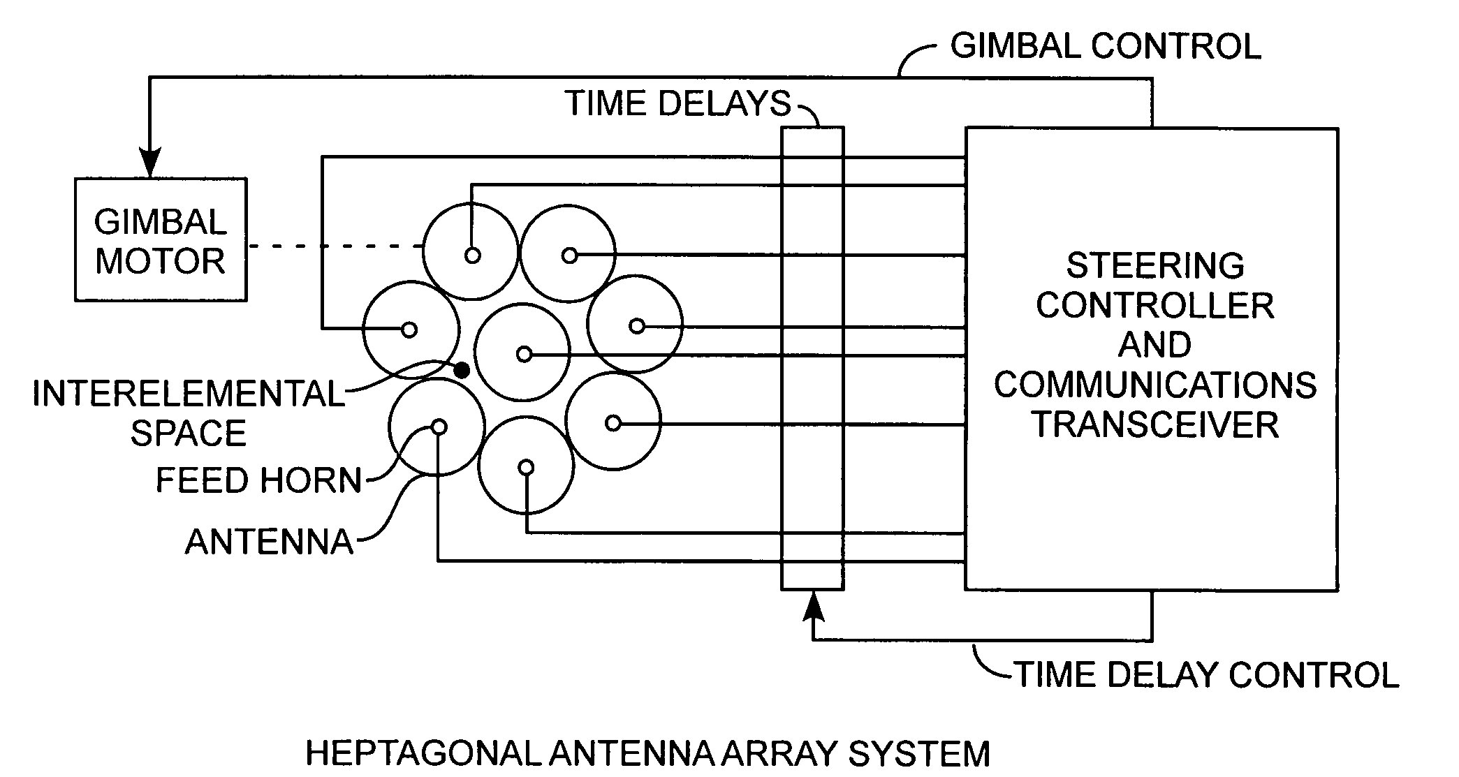
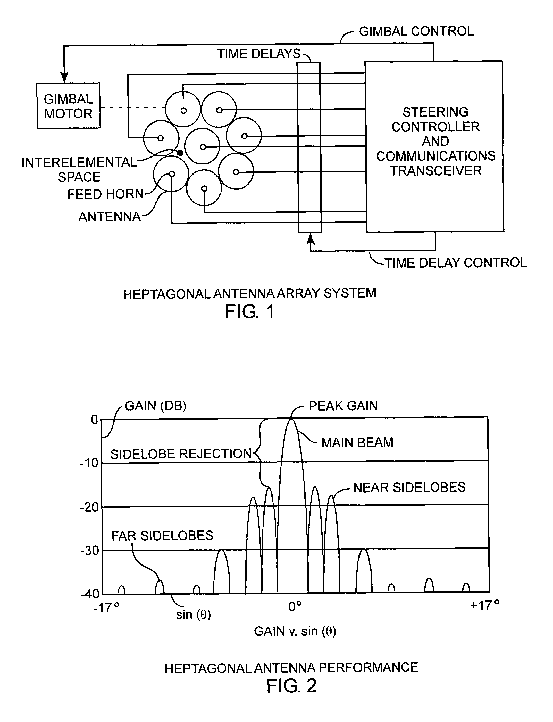
[0020]An embodiment of the invention is described with reference to the figures using reference designations as shown in the figures. Referring to FIG. 1, a heptagonal antenna array includes a center antenna element with seven surrounding antenna elements. Preferably, the seven surrounding elements are equiangularly disposed about the center antenna element. Preferably, the seven outer elements are in juxtaposed positions about the center element. As such, there is an interelemental space created between the center element and the outer elements, which interelemental space is disadvantageously, significantly increased. A steering controller and communications transceiver is conventionally attached to the array. The seven outer reflectors are positioned in a circle so as to touch, but do not overlap. There is equal separation between the innermost reflector and each of the outer reflectors. Preferably, the eight elements are identical reflector dish antennas, each having a respective...


PUM


Abstract

An antenna system includes a heptagonal antenna array having one center antenna element and seven circumferentially surrounding antenna elements offering improved near and far sidelobe rejection, which is well suited for mechanically-gimbaled and time delayed electrical steering antenna applications.

Description

[0001]The invention was made with Government support under contract No. FA8802-04-C-0001 by the Department of the Air Force. The Government has certain rights in the invention.FIELD OF THE INVENTION[0002]The invention relates to the field of communication electrical antennas and antenna arrays. More particularly, the present invention relates to a heptagonal antenna array.BACKGROUND OF THE INVENTION[0003]A measure of performance of an antenna design is the sidelobe pattern levels relative to a main beam and is measured in negative decibels (−dB). The sidelobes are measured in −dB from peak gain of the main beam down to the peak gain of the sidelobes that are nearest to the main beam in angular position. The desirable decrease in the peak gain of the sidelobe beams relative to the peak gain of the main beam is referred to herein as sidelobe rejection. Desirable high sidelobe rejection rejects unwanted interference and can further enhance imaging in imaging application. Sidelobe rejec...

Claims


Application Information

Patent Timeline
Patent Type & Authority Patents(United States)
IPC IPC(8): H01Q21/00
CPCH01Q3/08H01Q21/20H01Q21/064H01Q3/2682
Inventor BLOSS, WALTER L.HALL, II, ERIC K.KSIENSKI, DAVID A.MCKAY, JAMES P.
Owner THE AEROSPACE CORPORATION
Why Eureka
Try Eureka