Radio-frequency mixer arrangement

a mixer and frequency technology, applied in the field of radio frequency mixer arrangement, can solve problems such as noise at the modulator output, and achieve the effects of reducing the negative-feedback resistance, reducing the linearity of differential amplifiers, and high baseband amplitude withou

Inactive Publication Date: 2007-05-15
INTEL CORP
View PDF3 Cites 17 Cited by
  • Summary
  • Abstract
  • Description
  • Claims
  • Application Information

AI Technical Summary

Benefits of technology

[0011]On the basis of the present invention, the differential amplifier in the mixer cell and the antialiasing filter are not different circuit blocks, but rather are combined with the operational amplifier's feedback path and form a unit. The control loop with the operational amplifier means that substantially no distortions arise at the operational amplifier output.
[0013]The control in the form of a differential signal and the design of the operational amplifier with a differential output significantly improve the common-mode rejection.
[0020]The configuration of the present invention advantageously makes it possible for the operating point, on the one hand, and the amplitude of the signal, on the other, to be set independently of one another.
[0022]The differential or symmetrical design of the circuit in one example, particularly of the coupling between the differential amplifier output and the multiplier input, is advantageous particularly with respect to smaller interference signal influences.
[0029]Overall, reducing the negative-feedback resistance in a differential amplifier achieves a high baseband amplitude without reducing the linearity of the differential amplifier. As a result, virtually no distortions arise, advantageously, in the low-frequency baseband path, where distortions would otherwise appear as nonlinear mixing products at the radio-frequency output of the modulator.
[0032]It is advantageously possible to dispense with a discrete surface acoustic wave (SAW) filter at the modulator output without violating mobile radio specifications such as GSM (Global System for Mobile communication) in terms of transmission noise in the reception band.

Problems solved by technology

The feedback resistances and the operating current are the primary cause of the noise at the modulator output, besides the oscillator's phase noise.

Method used


Image

  • Radio-frequency mixer arrangement
  • Radio-frequency mixer arrangement
  • Radio-frequency mixer arrangement

Examples


Embodiment Construction

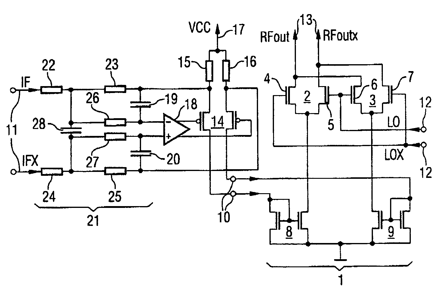
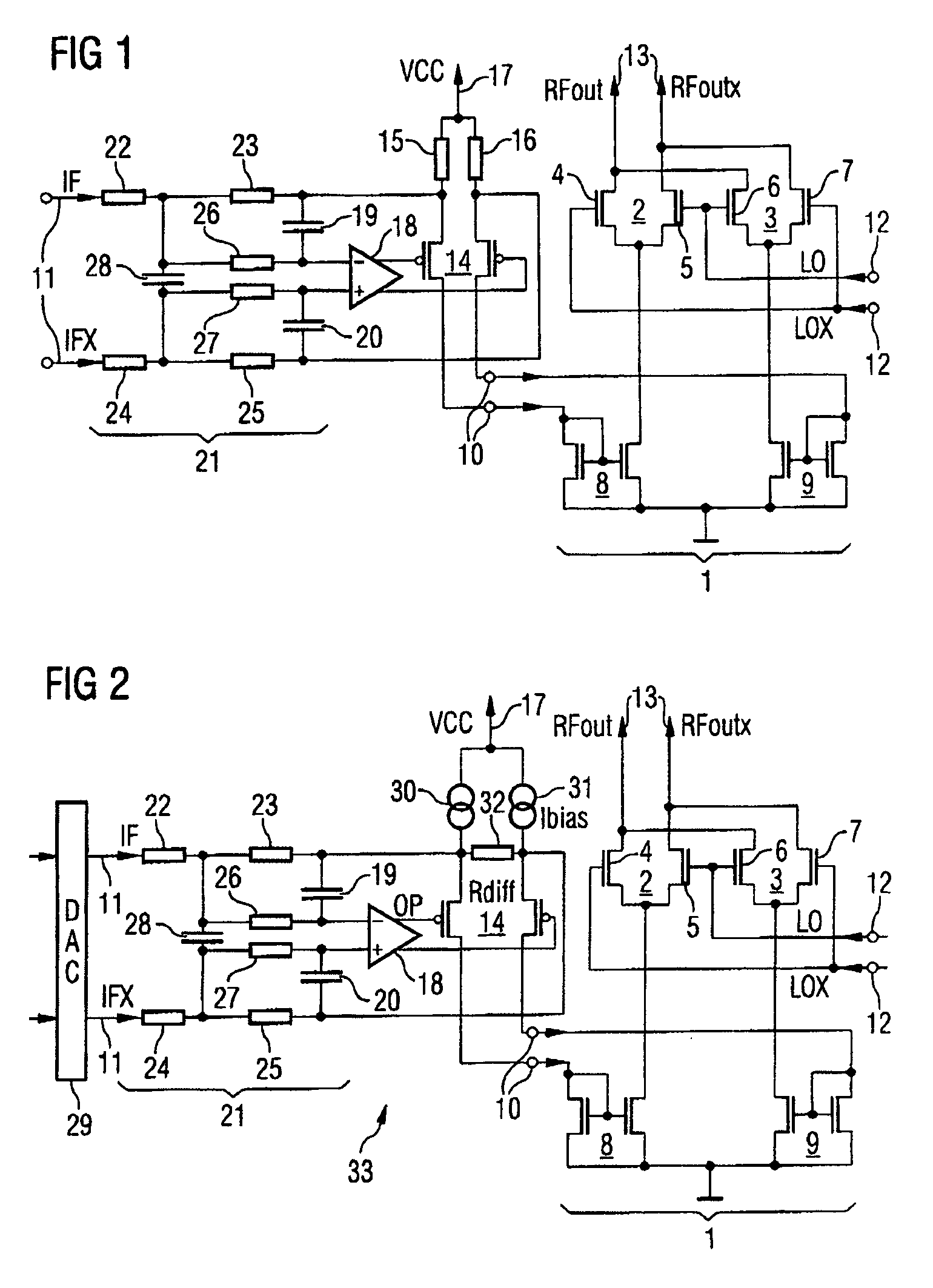
[0041]FIG. 1 shows a radio-frequency mixer arrangement having a Gilbert multiplier 1 which comprises two differential stages 2, 3. The differential stages 2, 3 each have two n-channel MOS differential transistors 4, 5; 6, 7 whose sources are connected to one another in respective pairs. The common source connections of the differential stages 2, 3 are connected to an input current interface 10 on the multiplier 1 via a respective current mirror 8, 9. A first signal input 11, which is designed to supply a differential signal and accordingly comprises two input terminals, is coupled to the current interface 10 via a block with an antialiasing filter, an operational amplifier and differential amplifier, as explained in more detail below. The first signal input 11 can have a baseband or intermediate frequency signal IF, IFX supplied to it.

[0042]A second signal input 12 on the multiplier 1 is likewise designed to supply a differential signal and, in the present case, is designed to suppl...


PUM


Abstract

The present invention relates to a radio-frequency mixer arrangement in which a differential amplifier is connected to an input on a multiplier. The differential amplifier is arranged together with at least one capacitance in the feedback path of an operational amplifier. The at least one capacitance performs the function of an antialiasing filter. The feedback operational amplifier with the design described results in a highly linear output signal given low output noise and a low current requirement. The mixer proposed is particularly suitable for use in vector modulators or polar modulators in transmission paths in mobile radios.

Description

REFERENCE TO RELATED APPLICATIONS[0001]This application claims the benefit of the priority date of German application DE 103 51 606.9, filed on Nov. 5, 2003, the contents of which are herein incorporated by reference in their entirety.FIELD OF THE INVENTION[0002]The present invention relates to a radio-frequency mixer arrangement.BACKGROUND OF THE INVENTION[0003]Radio-frequency mixer arrangements are used, by way of example, in vector modulators in order to convert a baseband signal which has undergone digital or analog modulation to a transmission frequency level. A vector modulator is constructed using integrated circuitry, normally with Gilbert multiplier cells.[0004]An integrated multiplier circuit which is suitable for use in vector modulators in radio transmission appliances is described by way of example in the document DE 101 32 802 A1. The multiplier circuit in this document has two input terminal pairs which are used for supplying a first and a second signal which are to b...

Claims


Application Information

Patent Timeline
Patent Type & Authority Patents(United States)
IPC IPC(8): G06F7/44G06F7/16H03C1/54H03D3/06H03D7/12H03D7/14H04B1/26
CPCH03D7/1441H03D7/1433H03D7/1458H03D7/1491H03D7/165H03D2200/0033H03D2200/0084
Inventor HANKE, ANDRESIMON, MARTIN
Owner INTEL CORP
Why Eureka
Try Eureka