Optical filtering structure in the visible and/or infrared domain

a filtering structure and visible and/or infrared technology, applied in the field of optical filtering structure, can solve the problems of degrading the signal-to-noise ratio of the device, unable to achieve the spectral response of coloured resin b>14/b>, and unable to achieve the spectral response of the colour resin

Active Publication Date: 2014-02-06
COMMISSARIAT A LENERGIE ATOMIQUE ET AUX ENERGIES ALTERNATIVES
View PDF8 Cites 19 Cited by
  • Summary
  • Abstract
  • Description
  • Claims
  • Application Information

AI Technical Summary

Benefits of technology

[0013]Another aim is to propose a filtering structure making it possible to carry out, in a juxtaposed manner, a first visible pass and infrared cut off filtering, and a second infrared pass and visible cut off filtering without having to resort to a black resin, which is adapted to function with a single detection and / or emission array in the visible and infrared domains, and which uses a lower number of dielectric layers than filtering structures of the prior art.
[0026]The use of a metal such as copper of which the real part of the refractive index has high values (greater than 1) in the visible domain moreover makes it possible to reduce the sensitivity of the angle of incidence of the first filter.
[0029]The alternation of dielectric layers of different refractive indices (for examplearound 2 for layers of SiN, and 1.45 for layers of SiO2) enables the formation of the first and the second filters such that they have different spectral responses but comprising a good transmission of the desired wavelengths (those of the visible domain for the first filter and those of the infrared domain for the second filter) and a good rejection of the other wavelengths.
[0030]By enabling a detection and / or an emission of several spectral bands on a same detection and / or emission array, a photodetector and / or photoemitter device using such a filtering structure can synchronise information (such as images) from the different channels (spectral responses), which reduces the complexity and the cost of making such a device compared to a device using several separate detection and / or emission arrays. It is thus possible to form several different spectral filters able to be integrated on a same detection and / or emission array. In addition, the filtering structure may be made via a relatively simple method and from materials conventionally used in micro-electronic foundries, unlike filtering structures of the prior art made only with dielectric materials (which must be deposited on external substrates and impose the use of several detection arrays, and / or involving a high number of dielectric layers, and particularly a high number of layers not common between the two filters) or requiring the presence of contaminant metals such as silver.
[0033]The presence of one or more additional metal layers in the second filter compared to the first filter makes it possible to avoid having to use, when the filtering structure is intended to carry out separate filterings on the one hand in the visible domain and on the other hand in the infrared domain, a black resin which is costly and complex to implement. The presence, in the first filter, of a number of metal layers less than that in the second filter makes it possible to minimise the absorption of visible light by the metal, disadvantageous in particular for blue and green, whereas the presence of a larger number of metal layers in the second filter makes it possible to improve the rejection of this filter in the visible domain.

Problems solved by technology

The spectral responses of coloured resins 14 do not make it possible, on their own, to reconstitute correctly the colours due to their non-negligible transmission in the near infrared domain.
Although such a device does not require an infrared cut off filter, the subtraction operation has the major drawback of degrading the signal to noise ratio of the device.
The problems exposed above are also found for an optical filtering structure intended to carry out filterings of different spectral bands only in the visible domain, or instead of different spectral bands only in the infrared domain.

Method used


Image

  • Optical filtering structure in the visible and/or infrared domain
  • Optical filtering structure in the visible and/or infrared domain
  • Optical filtering structure in the visible and/or infrared domain

Examples


first embodiment

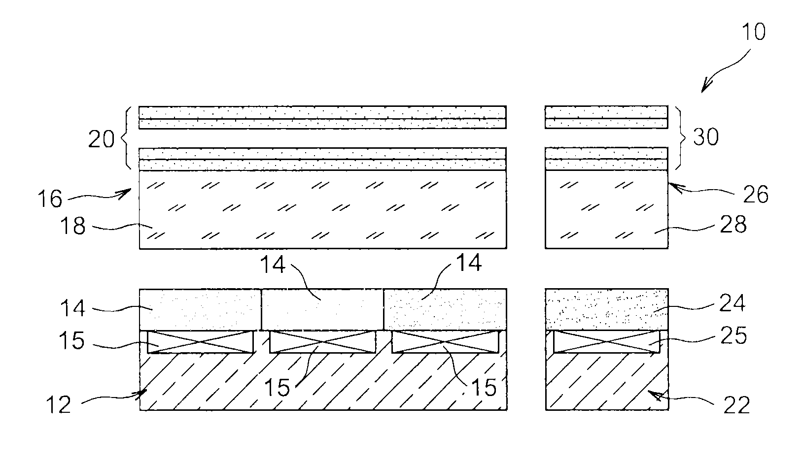
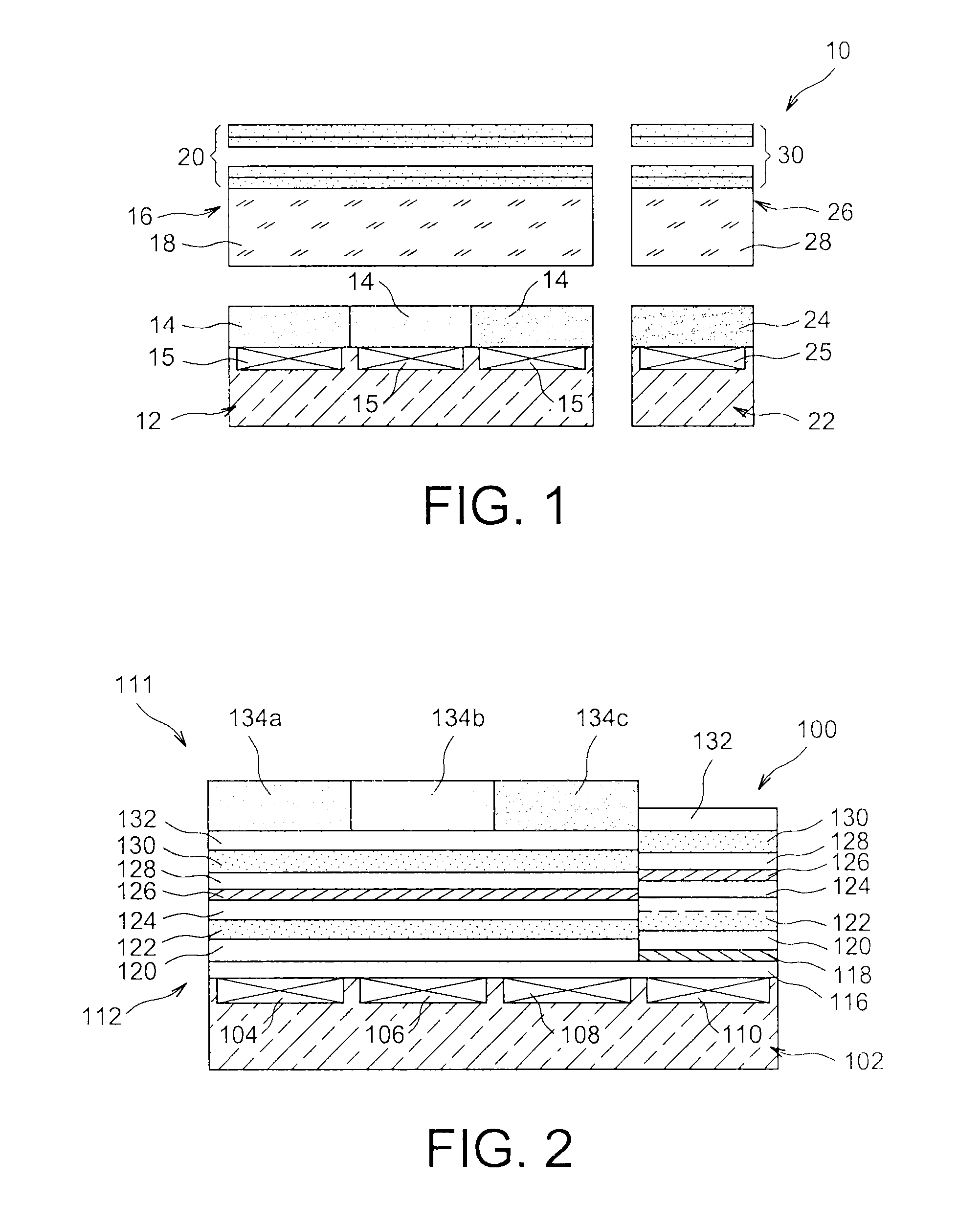
[0059]FIG. 2 represents partially and schematically a photodetector device comprising a filtering structure ;

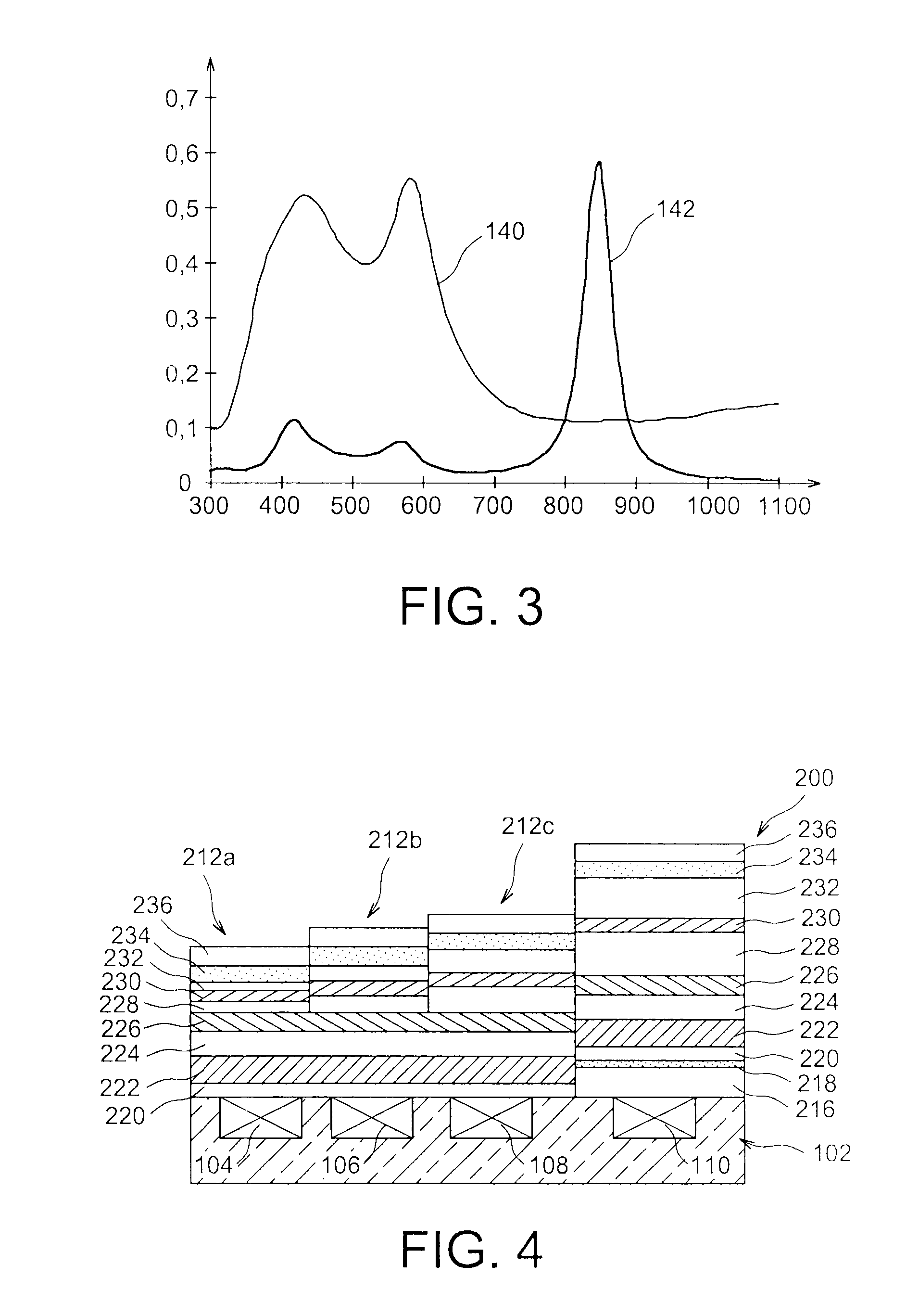
[0060]FIG. 3 represents the spectral responses of the filters of the filtering structure according to the first embodiment;

second embodiment

[0061]FIG. 4 represents partially and schematically a photodetector device comprising a filtering structure ;

[0062]FIG. 5 represents the spectral responses of the filters of the filtering structure according to the second embodiment;

[0063]FIGS. 6 and 7 represent the spectral responses of the filters of the filtering structure according to different variants of the first embodiment;

[0064]FIG. 8 represents the spectral responses of the filters of the filtering structure according to a variant embodiment.

[0065]Identical, similar or equivalent parts of the different figures described hereafter bear the same numerical references so as to make it easier to go from one figure to the next.

[0066]In order to make the figures more legible, the different parts (particularly the layers) shown in the figures are not necessarily according to a uniform scale.

[0067]The different possibilities (variants and embodiments) should be understood as not being mutually exclusive and may be combined together...


PUM


Abstract

An optical filtering structure comprising a stack of layers forming a first filter letting pass a first spectral band, and a second filter adjacent to the first filter and which lets pass a second spectral band comprising:a plurality of dielectric layers common to the two filters and of different refractive indices;n first metal layers common to the two filters;m second metal layers arranged only in the second filter;and wherein at least one of said dielectric layers comprises, in the first filter, a thickness different to that in the second filter, and / or wherein at least one dielectric layer is arranged only in the second filter;n being an integer greater than or equal to 0, and m being an integer greater than or equal to 1.

Description

TECHNICAL FIELD[0001]This document relates to an optical filtering structure comprising two adjacent optical filters, one letting pass a first spectral band and cutting off a second spectral band (for example of the visible pass and infrared cut off type), and the other letting pass the second spectral band and cutting off the first spectral band (for example of the infrared pass and visible cut off type). Such a filtering structure may for example he used in a photodetector and / or photoemitter type device to carry out, on a same light emission and / or reception support, both a filtering in the visible domain and a filtering in the infrared domain, particularly the near infrared, or instead different filterings in the visible domain.[0002]The invention may advantageously be used in the field of photodetector and / or photoemitter components having in particular the function of detecting and / or emitting light in different spectral bands according to the position on the component. Such a...

Claims


Application Information

Patent Timeline
Patent Type & Authority Applications(United States)
IPC IPC(8): G02B5/20G01J1/04G01J5/08
CPCG02B5/208G01J1/0437G01J5/0862G02B5/201G02B5/281G02B5/285H01L27/14621H01L31/02162Y10T29/49826G01J5/0802H01L31/0232
Inventor FREY, LAURENTARMAND, MARILYNPELLE, CATHERINE
Owner COMMISSARIAT A LENERGIE ATOMIQUE ET AUX ENERGIES ALTERNATIVES
Why Eureka
Try Eureka