Microphone Array Processor Based on Spatial Analysis

a microphone array and spatial analysis technology, applied in the field of microphone arrays, can solve the problems of limited improvement and often hindered communication in these applications, and achieve the effects of improving the spatial selectivity of the microphone array, enhancing target sources, and improving the rejection of interferen

Active Publication Date: 2009-04-23
CREATIVE TECH CORP
View PDF3 Cites 19 Cited by
  • Summary
  • Abstract
  • Description
  • Claims
  • Application Information

AI Technical Summary

Benefits of technology

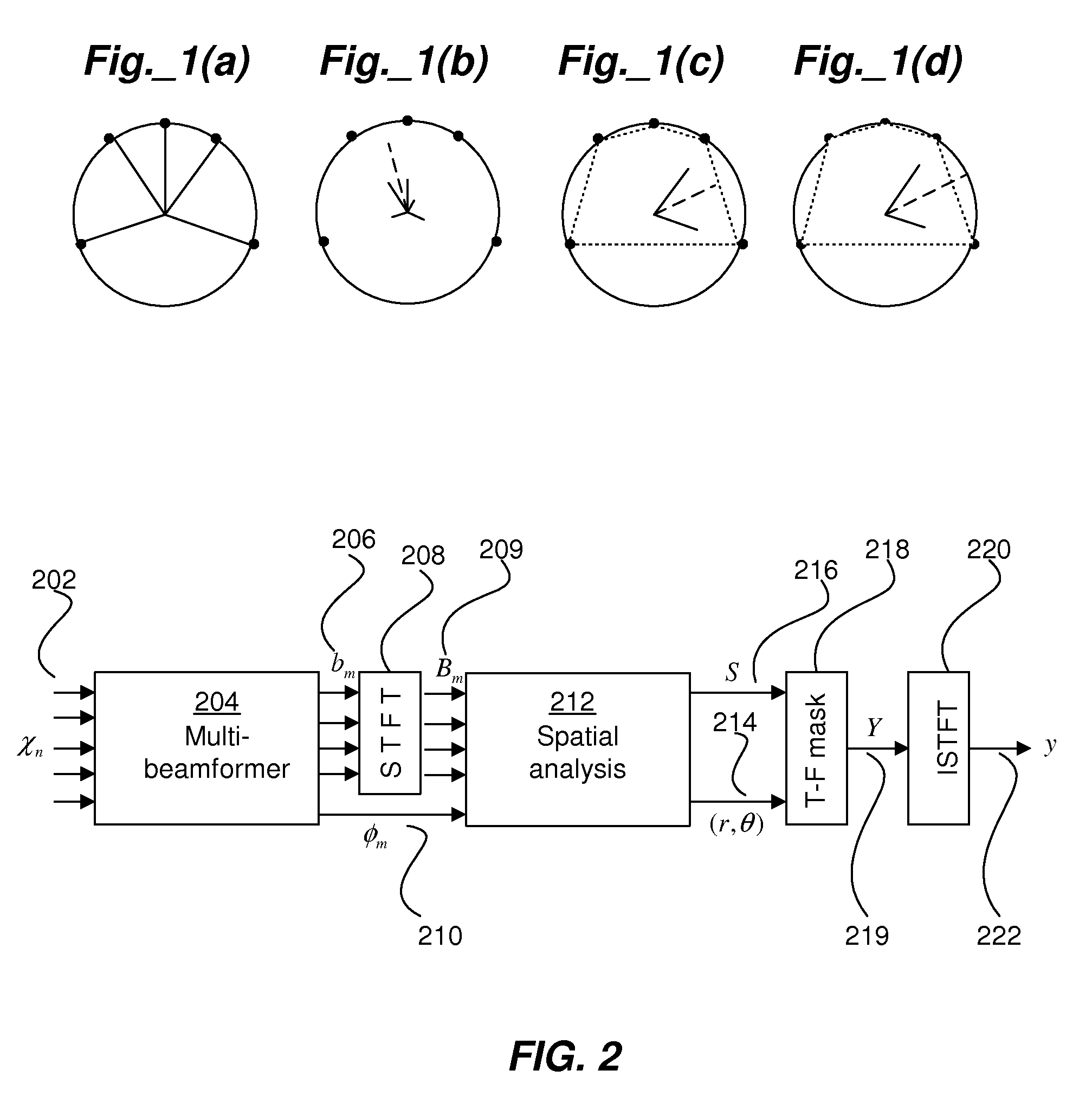
[0007]The present invention provides a beamforming and processing system that improves the spatial selectivity of a microphone array by forming multiple steered beams and carrying out a spatial analysis of the acoustic scene. The analysis derives a time-frequency mask that, when applied to a reference look-direction beam (or other reference signal), enhances target sources and substantially improves rejection of interferers that are outside of a specified target region.

Problems solved by technology

Unfortunately, the communication in these applications is often hindered by reverberation and interference from unwanted sound sources.
Microphone arrays have been previously used to improve speech reception in adverse environments, but small arrays based on linear processing such as delay-sum beamforming allow for only limited improvement due to low directionality and high-level sidelobes.

Method used


Image

  • Microphone Array Processor Based on Spatial Analysis
  • Microphone Array Processor Based on Spatial Analysis
  • Microphone Array Processor Based on Spatial Analysis

Examples


Embodiment Construction

[0016]Reference will now be made in detail to preferred embodiments of the invention. Examples of the preferred embodiments are illustrated in the accompanying drawings. While the invention will be described in conjunction with these preferred embodiments, it will be understood that it is not intended to limit the invention to such preferred embodiments. On the contrary, it is intended to cover alternatives, modifications, and equivalents as may be included within the spirit and scope of the invention as defined by the appended claims. In the following description, numerous specific details are set forth in order to provide a thorough understanding of the present invention. The present invention may be practiced without some or all of these specific details. In other instances, well known mechanisms have not been described in detail in order not to unnecessarily obscure the present invention.

[0017]It should be noted herein that throughout the various drawings like numerals refer to ...


PUM


Abstract

An array processing system improves the spatial selectivity by forming multiple steered beams and carrying out a spatial analysis of the acoustic scene. The analysis derives a time-frequency mask that, when applied to a reference look-direction beam (or other reference signal), enhances target sources and substantially improves rejection of interferers that are outside of the specified region.

Description

CROSS-REFERENCES TO RELATED APPLICATIONS[0001]This application is related to and incorporates by reference U.S. patent application Ser. No. 11 / 750,300, filed May 17, 2007, titled “Spatial Audio Coding Based on Universal Spatial Cues”, which incorporates by reference the disclosure of U.S. Provisional Application No. 60 / 747,532, filed May 17, 2006, the disclosure of which is further incorporated by reference in its entirety herein. Further, this application claims priority to and the benefit of the disclosure of U.S. Provisional Patent Application Ser. No. 60 / 981,458, filed on Oct. 19, 2007, and entitled “Enhanced Microphone Array Beamformer Based on Spatial Analysis” (CLIP231PRV), the entire specification of which is incorporated herein by reference in its entirety.BACKGROUND OF THE INVENTION[0002]1. Field of the Invention[0003]The present invention relates to microphone arrays. More particularly, the present invention relates to processing methods applied to such arrays.[0004]2. De...

Claims


Application Information

Patent Timeline
Patent Type & Authority Applications(United States)
IPC IPC(8): H04R3/00
CPCH04R3/005H04S2400/11H04R2430/20G10L15/20H04R1/40H04R3/00H04S3/00H04S7/30
Inventor GOODWIN, MICHAEL M.
Owner CREATIVE TECH CORP
Why Eureka
Try Eureka