Position measuring arrangement
a technology for positioning measurement and arrangement, applied in the direction of measuring devices, instruments, and optical conversion of sensor output, can solve the problems of increasing the complexity, and therefore the cost, of correspondingly constructed position measurement arrangement, and the increase of the outlay, or the cost, of such system
- Summary
- Abstract
- Description
- Claims
- Application Information
AI Technical Summary
Benefits of technology
Problems solved by technology
Method used
Image
Examples
first embodiment
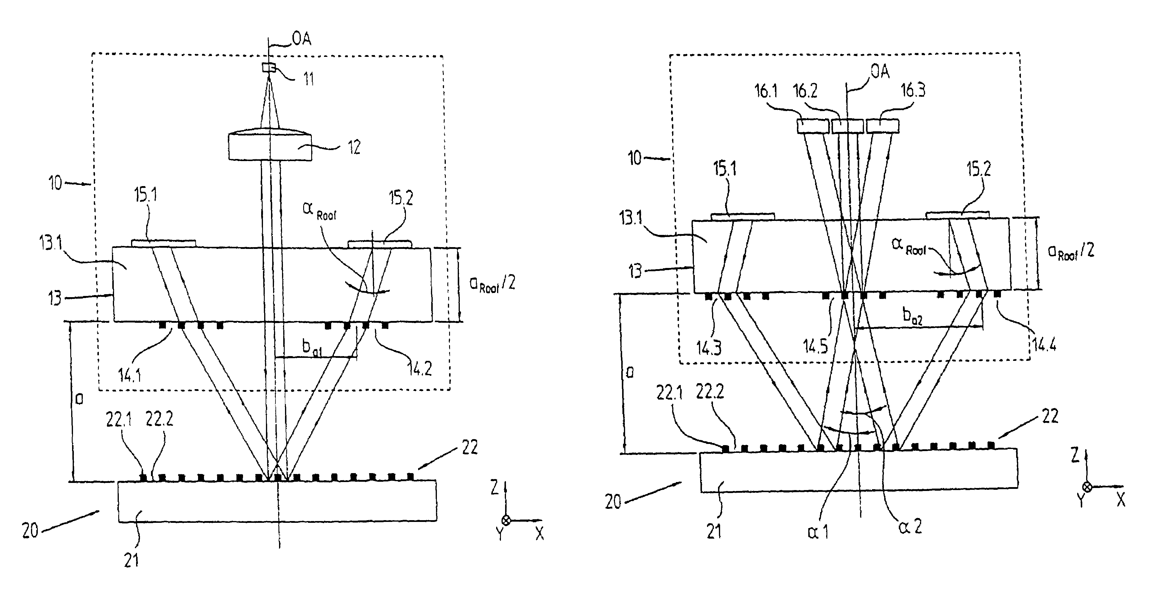
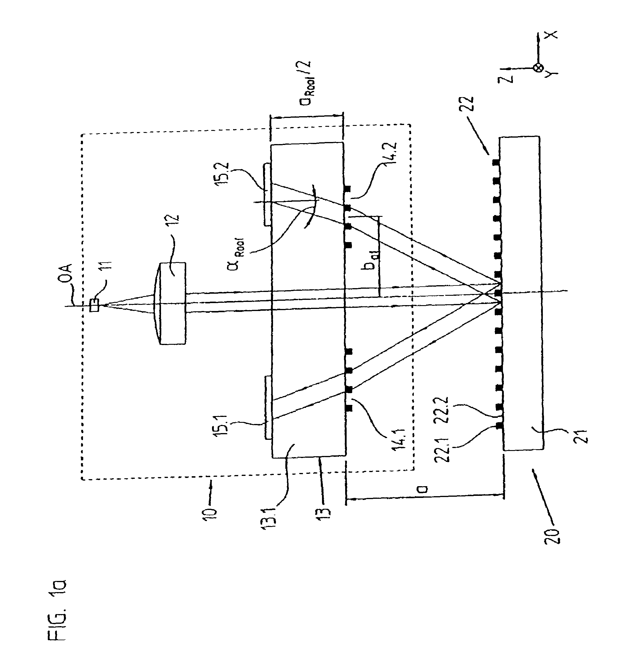
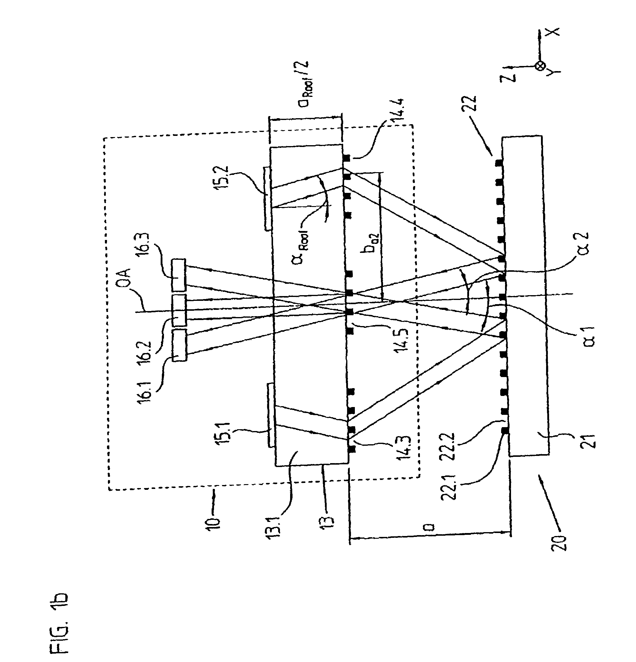
[0096]A first embodiment of the position measuring arrangement in accordance with the invention will be explained in what follows by FIGS. 1a to 1d. Here, FIGS. 1a and 1b respectively show in a schematized form partial scanning beam paths in a lateral view in the x-z plane. The scanning beam path from the light source 11 until the partial light beams impinge on the reflector elements 15.1, 15.2, is represented in FIG. 1a. FIG. 1b shows the scanning beam path following the partial light beams impinging on the reflector elements 15.1, 15.2 as far as the detector elements 16.1, 16.2, 16.3. FIGS. 1c and 1d respectively show views from above on the top and underside of the scanning plate 13 with the optical elements arranged there.
[0097]In this example, the position measuring arrangement in accordance with the present invention includes a reflection scale graduation 20, as well as a scanning unit 10, which can be moved in relation to it in at least one measuring direction x. The objects,...
second embodiment
[0132]A second embodiment of the position measuring arrangement in accordance with the present invention will be explained in what follows by FIGS. 3a to 3d. In principle, these drawing figures again show the same views of the position measuring arrangement as in the above example in FIGS. 1a to 1d.
[0133]In this example it has again been assured by the realized scanning beam path, or the arrangement of the various optical elements, in particular in the scanning unit 110, that a pair of light beams impinges in a non-parallel manner on the combining grating 114.5 in front of the detector elements, and several pairs of co-linear and interfering partial light beams are propagated downstream of the combining grating 114.5 in the direction of the detector elements 116.1 to 116.3.
[0134]The essential differences in regard to the first exemplary embodiment in FIGS. 1a to 1d will be explained in what follows. Thus, supplementing the first example it has been provided to arrange a splitting g...
third embodiment
[0163]A third embodiment of the position measuring arrangement in accordance with the present invention is represented in FIGS. 6a to 6d. Again, the representation corresponds to those of the previously explained in FIGS. 1a to 1d, 3a to 3d and 4a to 4d. Essentially only the definitive differences from these examples will be considered.
[0164]Thus, it has now been provided that the light beam, which is parallel after passing through the optical collimation device 412, impinges on a splitting grating 414.6 on the top of the scanning plate 413 and is split there into two partial light beams. Subsequently, both partial light beams reach an auxiliary splitting grating 414.7 on the underside of the scanning plate 413. By this auxiliary splitting grating 414.7 it is assured that the two split partial light beams impinge at the same impact location on the reflection scale representation 420. As can be seen in the view of FIG. 6d, the auxiliary splitting grating 414.7 can also include two se...
PUM
 Abstract
Description
Claims
Application Information
 - R&D
- Intellectual Property
- Life Sciences
- Materials
- Tech Scout
- Unparalleled Data Quality
- Higher Quality Content
- 60% Fewer Hallucinations
Browse by: Latest US Patents, China's latest patents, Technical Efficacy Thesaurus, Application Domain, Technology Topic, Popular Technical Reports.
© 2025 PatSnap. All rights reserved.Legal|Privacy policy|Modern Slavery Act Transparency Statement|Sitemap|About US| Contact US: help@patsnap.com


