Circuit arrangement for operating electric lamps

Inactive Publication Date: 2003-02-25
PATENT TREUHAND GESELLSCHAFT FUR ELECTRIC GLUEHLAMPEN MBH
View PDF13 Cites 4 Cited by
  • Summary
  • Abstract
  • Description
  • Claims
  • Application Information

AI Technical Summary

Benefits of technology

A further advantage of the circuit arrangement according to the invention is that, instead of a bistable shutdown device, a shutdown device constructed as a threshold switch can be used, which is more cost-effective and has a simpler construction. Although the shutdown device constructed as a threshold switch is not bistable and, in particular, is not able to ensure a stable shutdown state without further measures, since the device for deactivating the starting circuit has a means which is used to maintain the deactivated state of the starting

Problems solved by technology

This device comprises a resistor and a diode, via which the capacitor of the starting device is discharged after the inverter

Method used


Image

  • Circuit arrangement for operating electric lamps
  • Circuit arrangement for operating electric lamps

Examples


Embodiment Construction

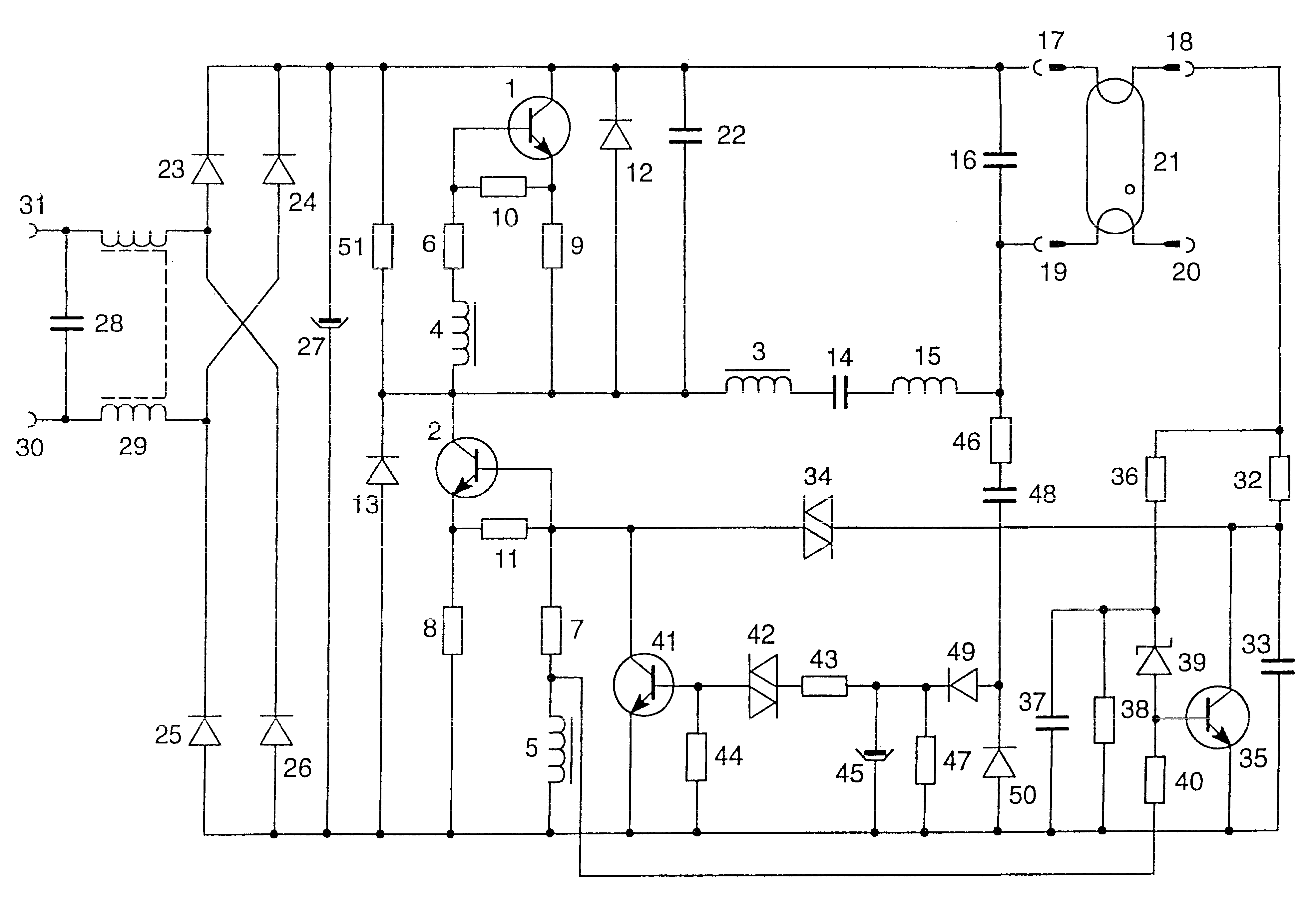
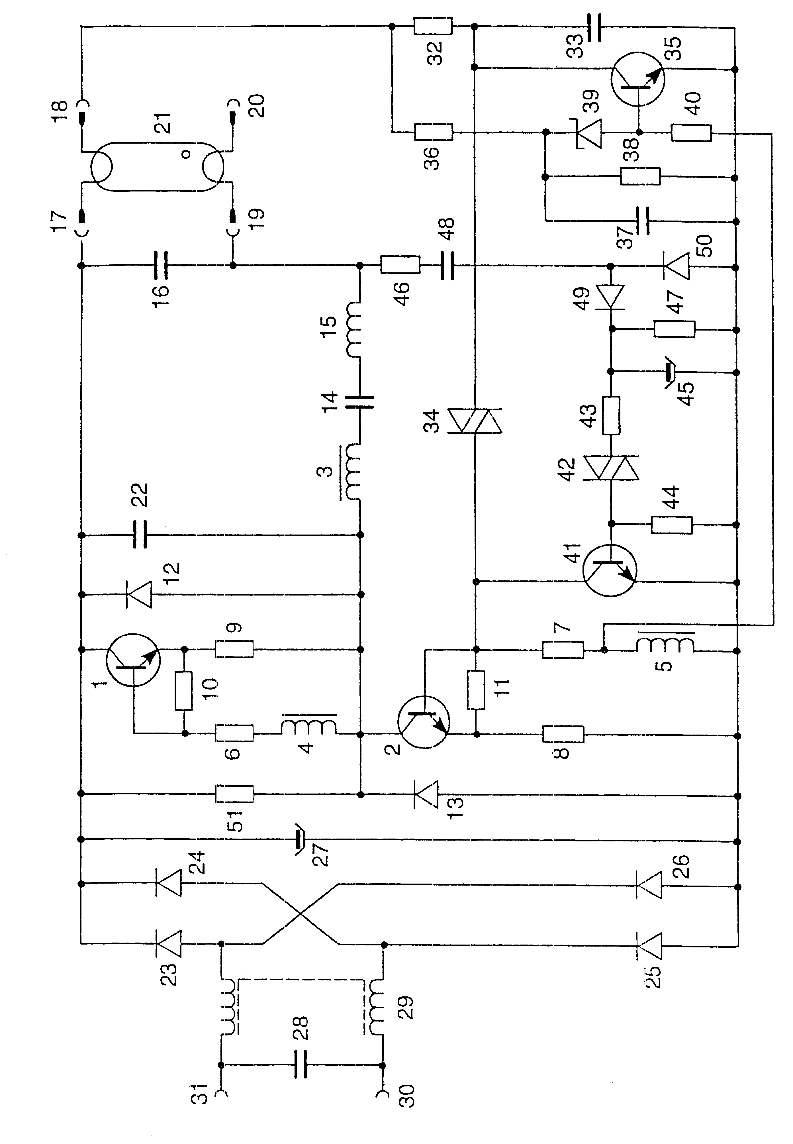
The invention will be explained in more detail below using a preferred exemplary embodiment. The FIGURE shows a schematic representation of a circuit diagram of the preferred exemplary embodiment of the circuit arrangement according to the invention.

The circuit arrangement depicted in the FIGURE is used to operate a low-pressure discharge lamp with an electrical power consumption of about 18 W. This circuit arrangement has a self-oscillating half-bridge inverter, which is substantially formed by the alternately switching transistors 1, 2 and the freewheeling diodes 12, 13 and the toroidal transformer 3-5. The toroidal transformer 3-5 is used to control the transistors 1 and 2. For this purpose, the primary winding 3 of the toroidal transformer is arranged in the load circuit, constructed as a series resonant circuit, of the half-bridge inverter, while the secondary windings 4 and 5 are in each case connected via a base bias resistor 6 and 7 to a base electrode of a half-bridge inver...


PUM


Abstract

The invention relates to a circuit arrangement for operating electric lamps, the circuit arrangement having an inverter for generating a medium or high-frequency supply voltage for one or more lamps (21) and a starting circuit for the inverter, and also a device for deactivating the starting circuit, the starting circuit comprising a voltage-dependent switching element (34) and a capacitor (33), and the device for deactivating the starting circuit comprising a switching means (35) whose switching path is arranged in parallel with the capacitor (33) of the starting circuit. According to the invention, the device for deactivating the starting circuit has a threshold switch (39) for controlling the switching means (35).

Description

PRIOR ARTA circuit arrangement of this type is described, for example, in the European publication EP 0 682 464 A1. This publication discloses a self-oscillating inverter having a starting circuit which is used to start the inverter oscillating. In addition, the circuit arrangement also has a device for deactivating the starting circuit. This device contains, as an important element, a transistor whose switching path, when switched on, forms a shunt around the charging capacitor of the starting circuit. After the inverter has begun oscillating, the transistor is switched on and the starting device is deactivated.The European publication EP 0 753 987 A1 describes a circuit arrangement having an inverter to apply a medium or high-frequency supply voltage to one or more lamps and having a starting circuit which is used to start the inverter oscillation. In addition, this circuit arrangement also has a device for deactivating the starting circuit. This device comprises a resistor and a ...

Claims


Application Information

Patent Timeline
IPC IPC(8): H05B41/285H05B41/28
CPCH05B41/2855
Inventor RUDOLPH, BERND
Owner PATENT TREUHAND GESELLSCHAFT FUR ELECTRIC GLUEHLAMPEN MBH
Why Eureka
Try Eureka