Eureka AIR delivers breakthrough ideas for toughest innovation challenges, trusted by R&D personnel around the world.

Method for measuring the position of a mark in a deflector system

a technology of deflector system and position measurement, which is applied in the direction of instruments, photomechanical devices, and using wave/particle radiation means, etc., can solve the problems of difficult time measurement accuracy and only being able to measure in the same direction from far

Active Publication Date: 2011-03-22
MICRONIC LASER SYST AB
View PDF12 Cites 3 Cited by
  • Summary
  • Abstract
  • Description
  • Claims
  • Application Information

AI Technical Summary

Benefits of technology

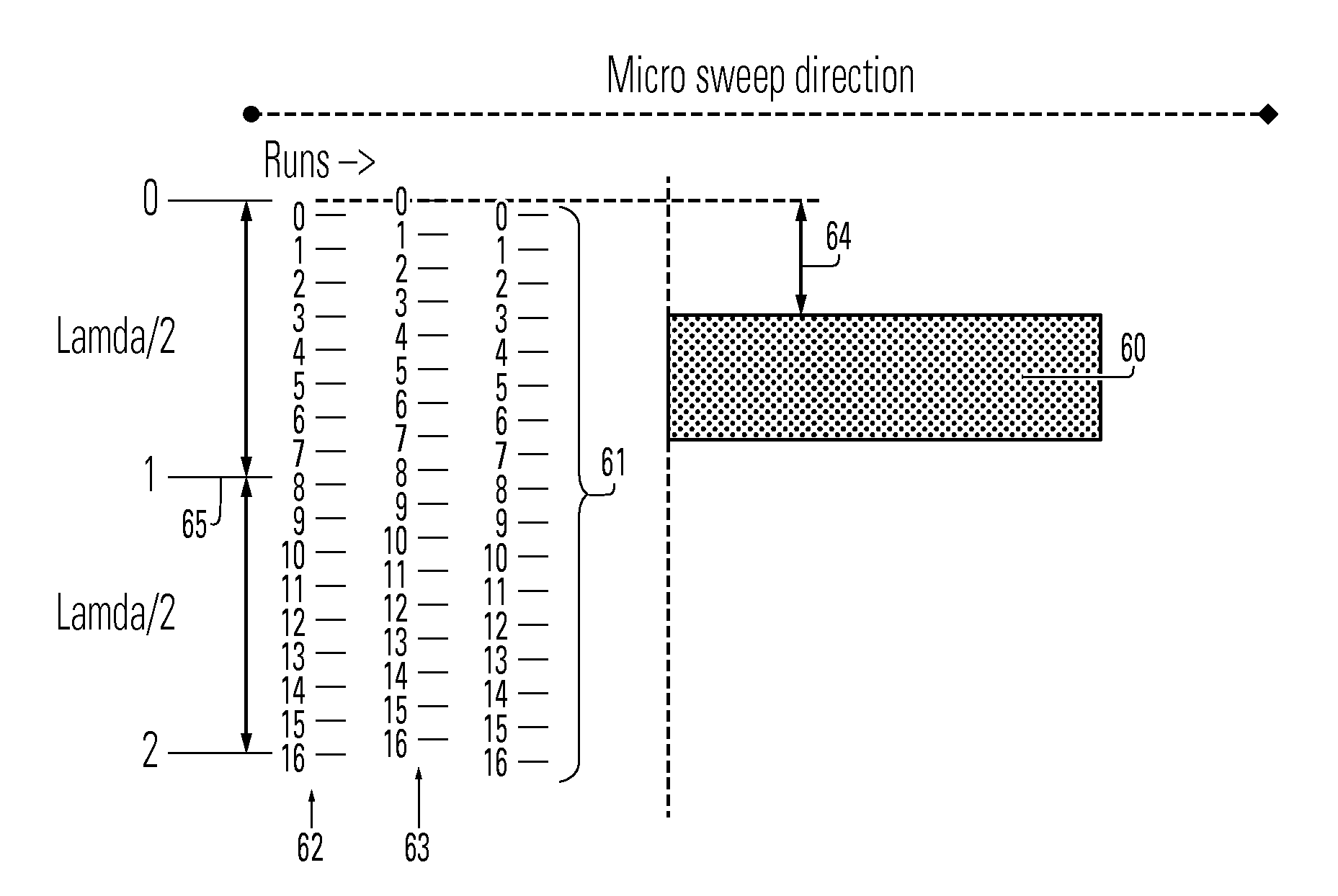
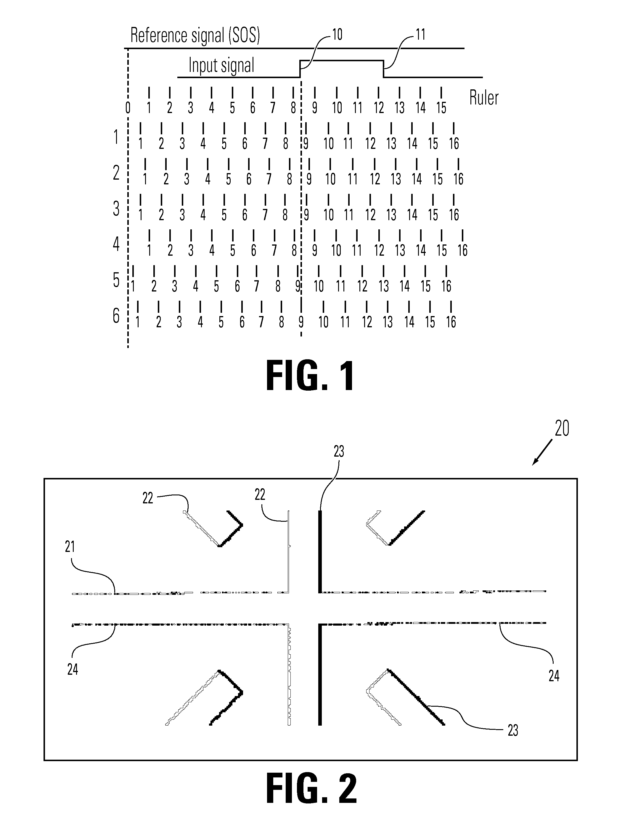
[0018]An advantage with the present invention is that it is possible to generate an image of the pattern without using any other detection method than the one we already are using today, since the present invention is similar to the prior art method, except that it is 90 degrees rotated.
[0019]Another advantage is that no new hardware is needed since the present invention is implemented in software.

Problems solved by technology

One drawback of the method used is that we so far only can measure in the same direction as the micro sweep.
It is difficult to measure time with high accuracy.

Method used


Image

  • Method for measuring the position of a mark in a deflector system
  • Method for measuring the position of a mark in a deflector system
  • Method for measuring the position of a mark in a deflector system

Examples


case 2

and in 2.00+ / −0.005

[0115]There is another very interesting way to see the physical conclusion of the case when d=0.

[0116]Assume that we want to measure a signal that is exactly k*tm. In this case the decimal part is zero. Now if we add counter ticks we must always count k ticks. Otherwise, and this is important, we should never get the correct average that is k in this case. In other words we cannot ever count k+1 ticks. If this would be the case the average we calculate would not be k. For this reasons the variance must be zero. Please note that only two numbers can generally be counted, k and k+1. So the value k−1 can never be counted. So in other words a count that is k+1 cannot be compensated by a value k−1 so we get the correct average anyway.

[0117]Since we do not know tp beforehand we should use the worst-case scenario when we estimate the error. In other words we shall say that the error due to the method is:

Error(K)=0.5*tm[ns].

[0118]This is as shown above the maximum of th...


PUM

PropertyMeasurementUnit
frequency measurementaaaaaaaaaa
frequencyaaaaaaaaaa
lengthaaaaaaaaaa

Abstract

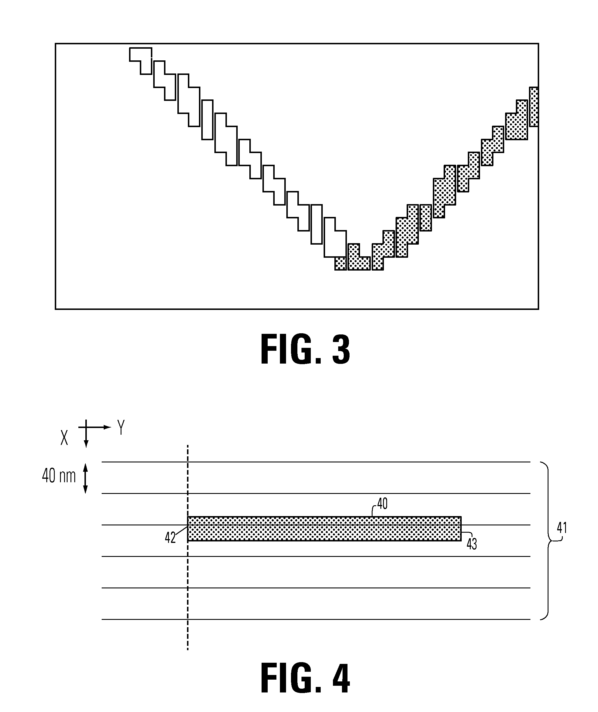
The present invention relates to a method for determining the coordinates of an arbitrarily shaped pattern in a deflector system. The method basically comprises the steps of: moving the pattern in a first direction (X), calculating the position of the edge of the pattern by counting the number of micro sweeps, performed in a perpendicular direction (Y), until the edge is detected, and determining the coordinates by relating the number of counted micro sweeps to the speed of the movement of the pattern. The invention also relates to software implementing the method.

Description

TECHNICAL FIELD[0001]The present invention relates to a method for determining the coordinates of an arbitrarily shaped pattern on a surface in a deflector system, as defined in claim 1 and 10. The invention also relates to software implementing the method for determining the coordinates of an arbitrarily shaped pattern on a surface in a deflector system, as defined in claim 14.BACKGROUND TO THE INVENTION[0002]The method used for measuring time in a deflector system has been used many years. Almost no modifications in the algorithm have been done so far. Only the pattern used for different kinds of calibrations has been modified during the years. Today we have an experimental verified repeatability of the method in the range of 10-15 nm over a surface of 800×800 mm. The 10-15 nm means here the measurement overlay.[0003]One drawback of the method used is that we so far only can measure in the same direction as the micro sweep. In order to measure an X-coordinate we therefore must use...

Claims


Application Information

Patent Timeline
Patent Type & Authority Patents(United States)
IPC IPC(8): G01B7/00G06K9/48G01B11/00G03F7/00
CPCG01B11/00G01B11/002G01B21/00
Inventor STIBLERT, LARSEKBERG, PETER
Owner MICRONIC LASER SYST AB
Why Eureka
Eureka Blog
Learn More