Position measuring arrangement

a technology of positioning and measuring arrangement, applied in the direction of measuring devices, converting sensor output optically, instruments, etc., can solve the problems of error signals becoming more and more generated, and erroneous interpretation of code elements, etc., to achieve great dependability, availability and dependability. great

Active Publication Date: 2010-11-16
DR JOHANNES HEIDENHAIN GMBH
View PDF20 Cites 3 Cited by
  • Summary
  • Abstract
  • Description
  • Claims
  • Application Information

AI Technical Summary

Benefits of technology

[0014]It is therefore an object of the present invention to provide an absolute position measuring arrangement, by which a correct absolute position is generated with great dependability, in connection with which availability and dependability are very great.
[0016]The present invention is furthermore based on the object of disclosing a method for determining an absolute position, by which generation of the absolute position as free of errors as possible is made possible.

Problems solved by technology

This has the disadvantage that, in case of a reduction of the amplitudes of the analog scanning signal in the course of operation, error signals are increasingly generated.
It is disadvantageous in this case that the states detected by this additional detector do not correspond to the states at the location of the code, so that erroneous interpretations of the code elements can occur.

Method used


Image

  • Position measuring arrangement
  • Position measuring arrangement
  • Position measuring arrangement

Examples


Embodiment Construction

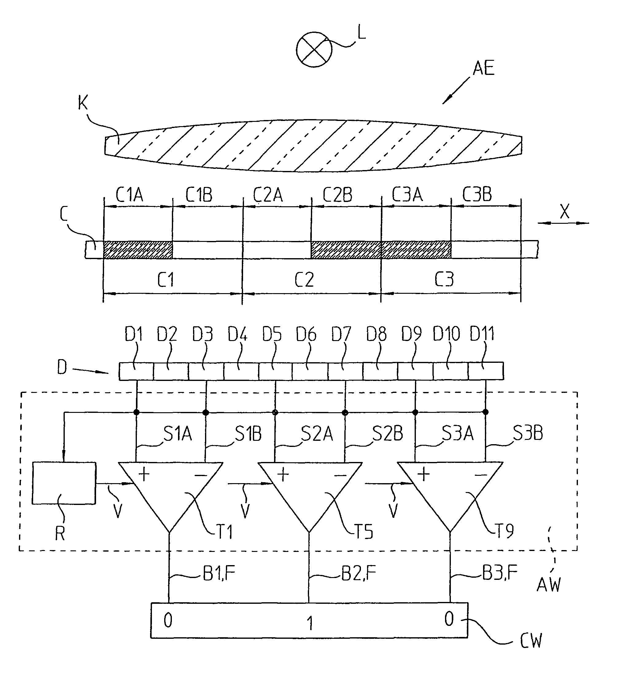
[0043]The present invention will be described by a code C, in which each code element C1, C2, C3 includes two partial fields, or respectively partial areas C1A, C1B, C2A, C2B, as well as C3A, C3B, which are designed inverted, or respectively complementary to each other. These partial fields can be arranged next to each other transversely with respect to the measuring direction X or, in a particularly advantageous manner, following each other in the measuring direction X, as represented in the example. For reasons of clarity, these partial areas will only be designated as A and B later on.

[0044]In this counter-phase arrangement, the code elements are designed in such a way that an at least approximately equal ratio of properties which are complementary to each other exists at least over the length of a respective scanning range, from which the reference value, which will be later described in greater detail, is obtained. It is assured by the counter-phase arrangement that the ratio i...


PUM


Abstract

A method for absolute position measuring that includes scanning a code having code elements arranged one behind the other in a measuring direction, wherein the code elements include sequential first and second code elements which define a code word containing absolute position information. The method including generating scanning signals within the first code elements and the second code elements. The method further including forming information regarding the sequential first and second code elements from the scanning signals via a reference value and determining the reference value as a function of at least one of the scanning signals within the first code elements and the scanning signals within the second code elements.

Description

RELATED APPLICATIONS[0001]Applicants claim, under 35 U.S.C. §119, the benefit of priority of the filing date of Sep. 22, 2007 of a German patent application, copy attached, Ser. No. 10 2007 045 362.2, filed on the aforementioned date, the entire contents of which is incorporated herein by reference.BACKGROUND[0002]1. Technical Field[0003]The present invention relates to a position measuring arrangement including a code having a sequence of code elements arranged one behind the other in the measuring direction, in which several sequential code elements each constitute a code word containing absolute position information. The arrangement further includes a scanning arrangement, having a detector unit with several detector elements for scanning the code elements, each of which constitutes a code word, and for forming at least one scanning signal within respectively one of the code elements. An evaluating unit with assessment arrangements, in which the at least one scanning signal of a ...

Claims


Application Information

Patent Timeline
Patent Type & Authority Patents(United States)
IPC IPC(8): G01B11/14G01D5/34
CPCG01D5/2457
Inventor MAYER, ELMAROBERHAUSER, JOHANN
Owner DR JOHANNES HEIDENHAIN GMBH
Why Eureka
Try Eureka