Unlock instant, AI-driven research and patent intelligence for your innovation.

Path setting method and communication apparatus in communication network performing communications through a plurality of layers

a communication network and plurality of layers technology, applied in the field of path setting method and communication apparatus in the communication network, can solve the problem that information concerning a request from an operator or user cannot be utilized when, and achieve the effect of efficiently utilizing network resources and reducing the total number of messages to be transferred

Inactive Publication Date: 2010-05-04
FUJITSU LTD
View PDF24 Cites 0 Cited by
  • Summary
  • Abstract
  • Description
  • Claims
  • Application Information

AI Technical Summary

Benefits of technology

[0019]In consideration of the above problems, an object of the present invention is to provide a path setting method and a communication apparatus enabling utilization of information concerning a request from an operator or a user at the time of calculation of the route of a path and enabling a decrease of the number of times of transfer of the path setting request message and the path setting acknowledgement message between the communication apparatuses.
[0031]By this, when it is necessary in a communication apparatus existing in the middle of the route of a path of the lower layer to calculate the route of this path, the path setting information included in the path setting request message of the higher layer can be utilized. Accordingly, the total number of messages to be transferred can be decreased.
[0032]By employing any of the above methods (1-1), (1-2), and (2), it becomes possible to utilize the information concerning a request from an operator or user in a communication apparatus for calculating the route of a path in a network that has a plurality of layers and must calculate the route of a path in a dispersed manner as covered by the present invention.
[0033]For this reason, it becomes possible to select a more optimal route for responding to a request from an operator or user. As a result, it becomes possible to further efficiently utilize network resources. Further, it becomes possible to set a plurality of paths by a smaller number of messages.

Problems solved by technology

(1) First, the first problem is that, as previously mentioned, there is a case where information concerning a request from an operator or user cannot be utilized when calculating the route of a path.

Method used


Image

  • Path setting method and communication apparatus in communication network performing communications through a plurality of layers
  • Path setting method and communication apparatus in communication network performing communications through a plurality of layers
  • Path setting method and communication apparatus in communication network performing communications through a plurality of layers

Examples


embodiment 1

[0109]FIG. 1 is a view of Embodiment 1 based on the present invention (first); and

[0110]FIG. 2 is the same view (second).

[0111]When looking at the path setting method executed in Embodiment 1 expressed in FIG. 1 and FIG. 2, it is as follows.

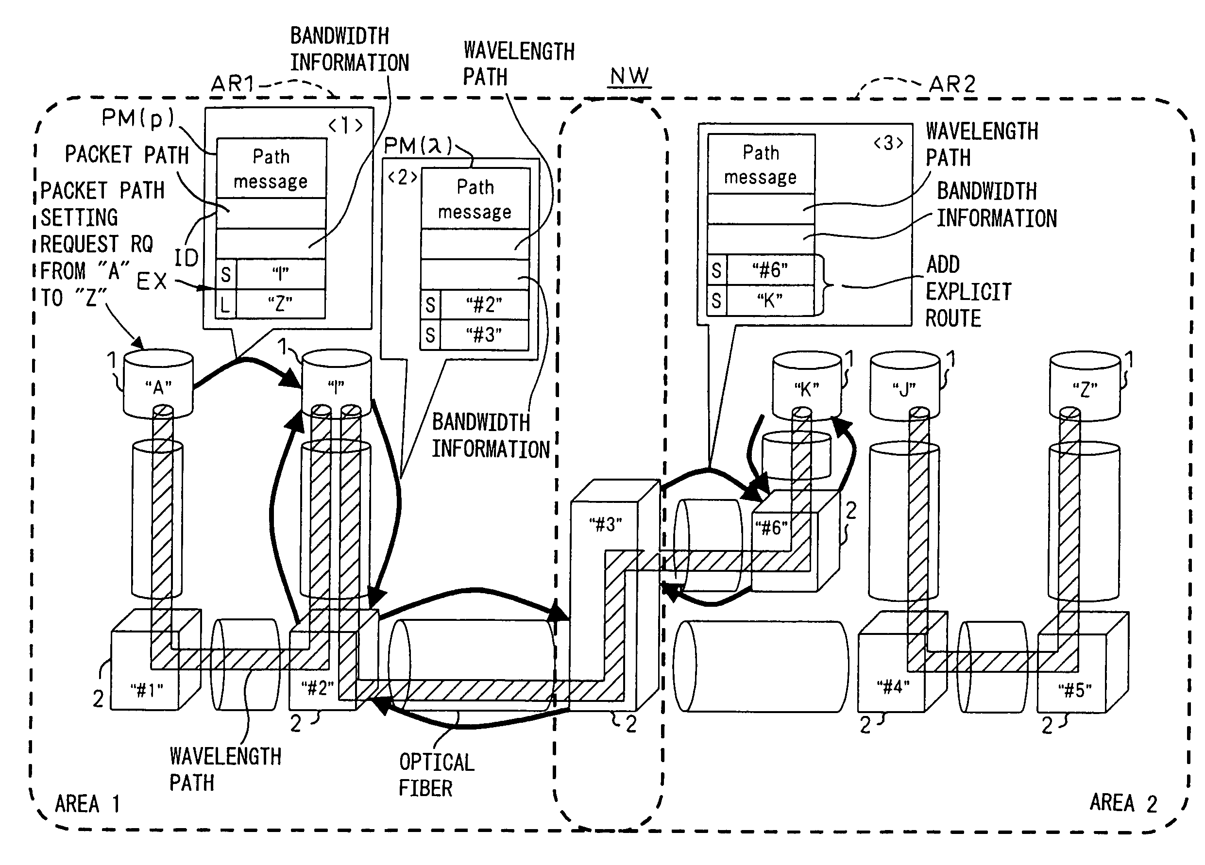
[0112]First, the communication network to which the path setting method is applied is a communication network having paths of a higher layer (for example a packet layer) and paths of a lower layer (for example a wavelength layer) formed in a hierarchy and performing communication between a first communication apparatus 1 (for example “A”) and a second communication apparatus 1 (for example “Z”) for which path setting is carried out by repeating through at least one other communication apparatus (“I”, “#1” to “#5”, “K”, “J”, etc.) in the middle of the path. The path setting method has at least the following steps S11, S12, and S13.

[0113]Step S11: Judging the existence of the possibility of reaching the second communication apparatus 1“Z” in the hi...

embodiment 2

[0135]FIG. 5 is a view of Embodiment 2 based on the present invention (first); and

[0136]FIG. 6 is the same view (second).

[0137]FIG. 7 is the same view (third).

[0138]When looking at steps S21, S22, and S23 for the path setting method executed in Embodiment 2 expressed in FIG. 5, FIG. 6, and FIG. 7, they are as follows.

[0139]Step S21: Judging the existence of the possibility of reaching the second communication apparatus 1“Z” in the higher layer in the repeating use communication apparatus 1 (for example “I”) existing in the middle of the path, after the higher layer path setting request message PM(p) requesting path setting by the higher layer (for example the packet layer) from the first communication apparatus 1“A” to the second communication apparatus 1“Z” is originated.

[0140]Step S22: Generating the lower layer path setting request message PM(λ) requesting path setting by the lower layer in the repeating use communication apparatus 1“I” when it is judged there is no possibility o...

embodiment 3

[0168]FIG. 9 is a view of Embodiment 3 based on the present invention (first);

[0169]FIG. 10 is the same view (second); and

[0170]FIG. 11 is the same view (third).

[0171]The present Embodiment 3 is a modification of the above Embodiment 2. The difference of the two resides in that the areas (above explained AR1 and AR2) are not considered in Embodiment 3. That is, the area in Embodiment 3 is regarded as one network.

[0172]In such a network, under the dispersed routing protocol, the topology information etc. are flooded and a transmission delay occurs. This causes competition of resources. Then, finally, competition of the bandwidth and label occurs between communication apparatuses and the signaling ends unsuccessfully.

[0173]FIG. 9 to FIG. 11 show how the present invention can avoid such a problem. Below, Embodiment 3 will be explained in detail by referring to FIG. 9 to FIG. 11.

[0174]In the communication network NW, the communication apparatuses 1 and 2 know the information of all topo...


PUM


Abstract

A path setting method enabling utilization of request information from a user in a communication network having a path of a higher layer and a path of a lower layer formed in a hierarchy and performing communication between one communication apparatus and another communication apparatus for which a path is set by repeating through another communication apparatus. This method has a step of judging a possibility of reaching the destination communication apparatus in the higher layer, judged in the communication apparatus existing in the middle of the path, a step of transmitting a lower layer path setting request message obtained by further adding route designating information and bandwidth information in a higher layer path setting request message when it is judged there is no possibility of reaching the apparatus, and a step of notifying the transmitted lower layer path setting request message to each communication apparatus on the route reaching the destination communication apparatus.

Description

CROSS REFERENCE TO RELATED APPLICATION[0001]The present application is a continuation application of International application No. PCT / JP03 / 06147, filed on May 16, 2003, the contents being incorporated herein by reference.TECHNICAL FIELD[0002]The present invention relates to a path setting method and a communication apparatus in a communication network having a plurality of layers and performing communication between communication apparatuses through a path set by for example a signaling mechanism.[0003]Here, “a plurality of layers” means the layers in the case where there are a plurality of types of layers for setting a path reaching a reception side communication apparatus for receiving information of a transmission side communication apparatus transmitting information. Giving an example, there are currently a layer for setting a path by switching packets, that is, a packet path layer, a layer for setting a path by switching the wavelength of light, that is, a wavelength path laye...

Claims


Application Information

Patent Timeline
Patent Type & Authority Patents(United States)
IPC IPC(8): G01R31/08H04L12/28H04L45/50
CPCH04L45/00
Inventor MIYABE, MASATAKE
Owner FUJITSU LTD
Features
  • R&D
  • Intellectual Property
  • Life Sciences
  • Materials
  • Tech Scout
  • Unparalleled Data Quality
  • Higher Quality Content
  • 60% Fewer Hallucinations
Learn More