Method and apparatus for controlling automatic lifting and lowering type platform

a technology of lifting and lowering and controlling method, which is applied in the direction of transportation items, loading/unloading vehicle arrangment, refuse collection, etc., can solve the problems of affecting the maintenance of the crane, affecting affecting the operation of the crane. , to achieve the effect of ensuring the safety of the crew, facilitating and smoothing, and reducing the risk of accidents

Inactive Publication Date: 2010-05-11
KOUKEN CO LTD
View PDF15 Cites 14 Cited by
  • Summary
  • Abstract
  • Description
  • Claims
  • Application Information

AI Technical Summary

Benefits of technology

[0018]A first purpose of the present invention is to provide an automatic lifting and lowering controlling method and an automatic lift / lower type platform controlling apparatus for mobile power generating apparatus, or the like, that, in an automatic lifting / lowering operation on a mobile power generating apparatus, or the like, generate no strain and torsion which may cause failure or trouble of the apparatus.
[0038]In addition, by adopting a wireless remote control apparatus for starting / switching-over of the two operations of automatic lifting and lowering to limit the switch operation to only the two directions of lifting and lowering, automatic lifting / lowering operation can be carried out easily and smoothly, with the situation of the automatic lifting / lowering operation being grasped by the crew member who is also capable of paying attention to the safety of himself.

Problems solved by technology

However, loading and unloading of a mobile power generating apparatus, or the like, with a crane and by lashing work has presented a number of problems, such as that the operator of a crane is limited to the qualified personnel; that, if the crane used is large-sized, a wide working area is required to be secured, and that there is a hazard to the crew by a possible drop of load during operation of the crane, and the possibility of the load being damaged by dropping.
However, the automatic lifting / lowering platform apparatus A′ as disclosed in the patent literature 1 has presented such problems as that, due to the difference in distance from the single pressure source to the respective jacks as automatic lifting and lowering means, the pressure loss and the pressure transfer rate vary, resulting in differences in operation timing and operation speed between jacks, and thus the vertical positions of the respective jacks vary, which can cause an inclination to be generated in automatic lifting or automatic lowering of the power generator, and thus a strain or a torsion to be produced, resulting in the joint waterproofing material on the outer plate panel being peeled off, which may lead to rainwater entering the interior and the door becoming impossible to be opened.
In addition, there has been a big problem that, if, as the frame structural material αa′ for the chassis α′ in the automatic lifting / lowering platform apparatus A′, the above-mentioned channel steel material is used, and for further reinforcement, an upper part structural material (a-H frame) and five-face outer plates and a bottom plate as shown in FIG. 8 (a), are provided, those materials may interfere with some component parts of the power generator, with the bottom plate having such a maintenability ill effect as that the oil pan cannot be removed, and in order to avoid these possible issues, the automatic lifting / lowering platform apparatus A′ has to be increased in size, which results in an increase in the weight as opposed to the lightweight which is required of the automatic lifting / lowering platform apparatus for mobile power generating apparatus.
Such tension is transferred to the vibration absorbing rubber mounts and the outer plate panels, and the repetition of application of the tension has also caused the above-mentioned problems.
With the crane for loading and unloading, the shock is alleviated by the deflection of the long beams and the extension and contraction of the wires, but with the automatic lifting / lowering platform apparatus A′, there are no portions which can alleviate the shock, and thus the chassis is directly subjected to deflection and torsion, which can lead to occurrence of problems.
The inclination of the entire power generating apparatus can be easily verified at a location distant to some degree therefrom, however, the system with which the solenoid directional control valves are directly operated near the machine, the angle of the inclination cannot easily be recognized (the tardiness of angle recognition), which, in some cases, has led to an unnecessary inclination, and increased the shock load.
The tardiness of angle recognition involved in the operation near the machine might cause overturning of the machine, resulting in the operator himself being injured by the overturned machine, thus with this system, the operator must have had to repeat a slight adjustment, and “a patrol around and inspection of the entire machine”.

Method used


Image

  • Method and apparatus for controlling automatic lifting and lowering type platform
  • Method and apparatus for controlling automatic lifting and lowering type platform
  • Method and apparatus for controlling automatic lifting and lowering type platform

Examples


example

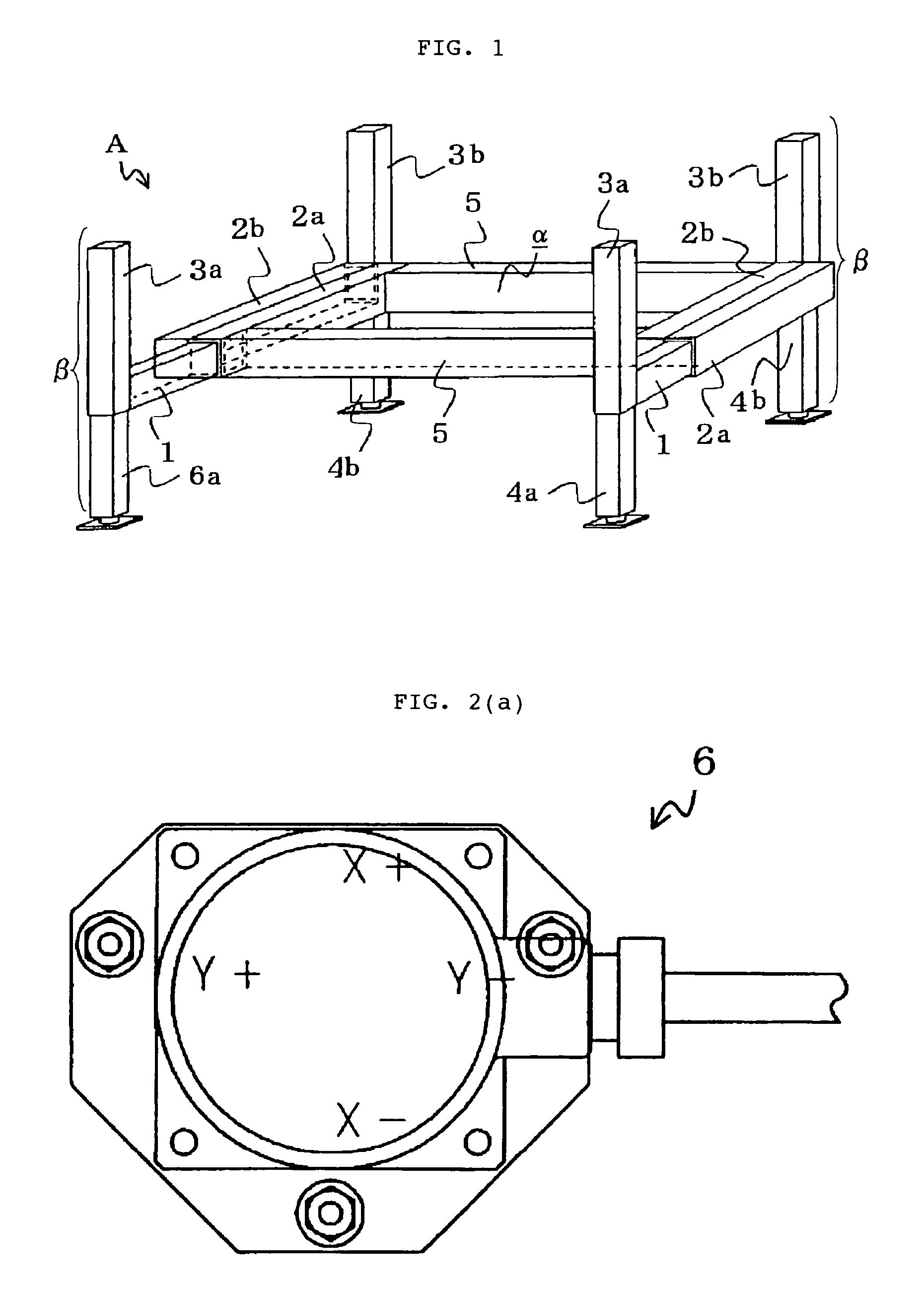
[0067]For the automatic lifting / lowering platform mechanism part to be with the mobile power generating apparatus B, or the like, development of a unique chassis α which can withstand the load for two-point support without the need for increasing the weight has been presented as a problem to be solved.

[0068]1) Herein, reinforcement of the chassis α will be described in detail.

[0069]Because the chassis α′ using the conventional type frame structural material αa′ made of channel steel is susceptible to a torsion moment, the conception has been transformed to adopt the concept of “torque tube” for bearing the torsion moment. For a given weight per unit length, a circular steel pipe provides a material having the highest strength for use as a torque tube 5, however, if the circular steel pipe is used, there arise difficulties of insufficient vertical load bearing capacity and workability, and it has been found that these difficulties can be solved by using a long square pipe as a torque...


PUM


Abstract

Disclosed is a method and apparatus for controlling automatic lifting and lowering type platform that can correct the inclination of a mobile power generator and that can always maintain the level while carrying out automatic lifting and lowering of the generator. The apparatus includes vertical outer cases which are extended or withdrawn in the horizontal directions from or into both sides at both ends of the chassis α; vertical inner cases which are inserted into the vertical outer cases and extended or withdrawn in the vertical directions; and an allotter which allots output to jacks so that inclination detected by an angle sensor can always be corrected.

Description

BACKGROUND OF THE INVENTION[0001]1. Field of the Invention[0002]The present invention relates to an automatic lifting and lowering controlling method that serves in installation of a heavy machine, such as a mobile power generating apparatus, or the like, on or removal thereof from a desired site, and an automatic lift / lower type platform controlling apparatus which is to be directly used for implementing the method.[0003]2. Description of the Related Art[0004]Conventionally, installation of a mobile power generating apparatus, or the like, on or removal thereof from a desired site has been performed by using a mobile large-sized crane, or the like, and the lashing crew therearound handling slings and other materials for load lashing.[0005]However, loading and unloading of a mobile power generating apparatus, or the like, with a crane and by lashing work has presented a number of problems, such as that the operator of a crane is limited to the qualified personnel; that, if the crane...

Claims


Application Information

Patent Timeline
Patent Type & Authority Patents(United States)
IPC IPC(8): B60P1/64B66C15/06B66F11/04
CPCB66F7/20
Inventor MATSUMOTO, KESAFUMI
Owner KOUKEN CO LTD
Why Eureka
Try Eureka