Head unit and method of setting the same; drawing system; methods of manufacturing liquid crystal display device, organic el device, electron emitting device, pdp device, electrophoresis display device, color filter, and organic el; and methods of forming spacer, metal wiring, lens, resist, and light diffuser

a technology of a head unit and a setting device, applied in the direction of electrode system manufacturing, electric discharge tube/lamp manufacturing, instruments, etc., can solve the problems of short circuit and troublesome connection and disconnect operation

Inactive Publication Date: 2005-03-29
KATEEVA
View PDF4 Cites 23 Cited by
  • Summary
  • Abstract
  • Description
  • Claims
  • Application Information

AI Technical Summary

Benefits of technology

As described above, by applying the above-described head unit to the method of manufacturing a color filter, the method of manufacturing an organic EL, the spacer-forming method, the metal wiring-forming method, the lens-forming method, the resist-forming method, and the light diffuser-forming me...

Problems solved by technology

These connecting and disconnecting operations are not only troublesome but are also subject to possible causes for a short circuit due to the adhesion to ...

Method used


Image

  • Head unit and method of setting the same; drawing system; methods of manufacturing liquid crystal display device, organic el device, electron emitting device, pdp device, electrophoresis display device, color filter, and organic el; and methods of forming spacer, metal wiring, lens, resist, and light diffuser
  • Head unit and method of setting the same; drawing system; methods of manufacturing liquid crystal display device, organic el device, electron emitting device, pdp device, electrophoresis display device, color filter, and organic el; and methods of forming spacer, metal wiring, lens, resist, and light diffuser
  • Head unit and method of setting the same; drawing system; methods of manufacturing liquid crystal display device, organic el device, electron emitting device, pdp device, electrophoresis display device, color filter, and organic el; and methods of forming spacer, metal wiring, lens, resist, and light diffuser

Examples


Embodiment Construction

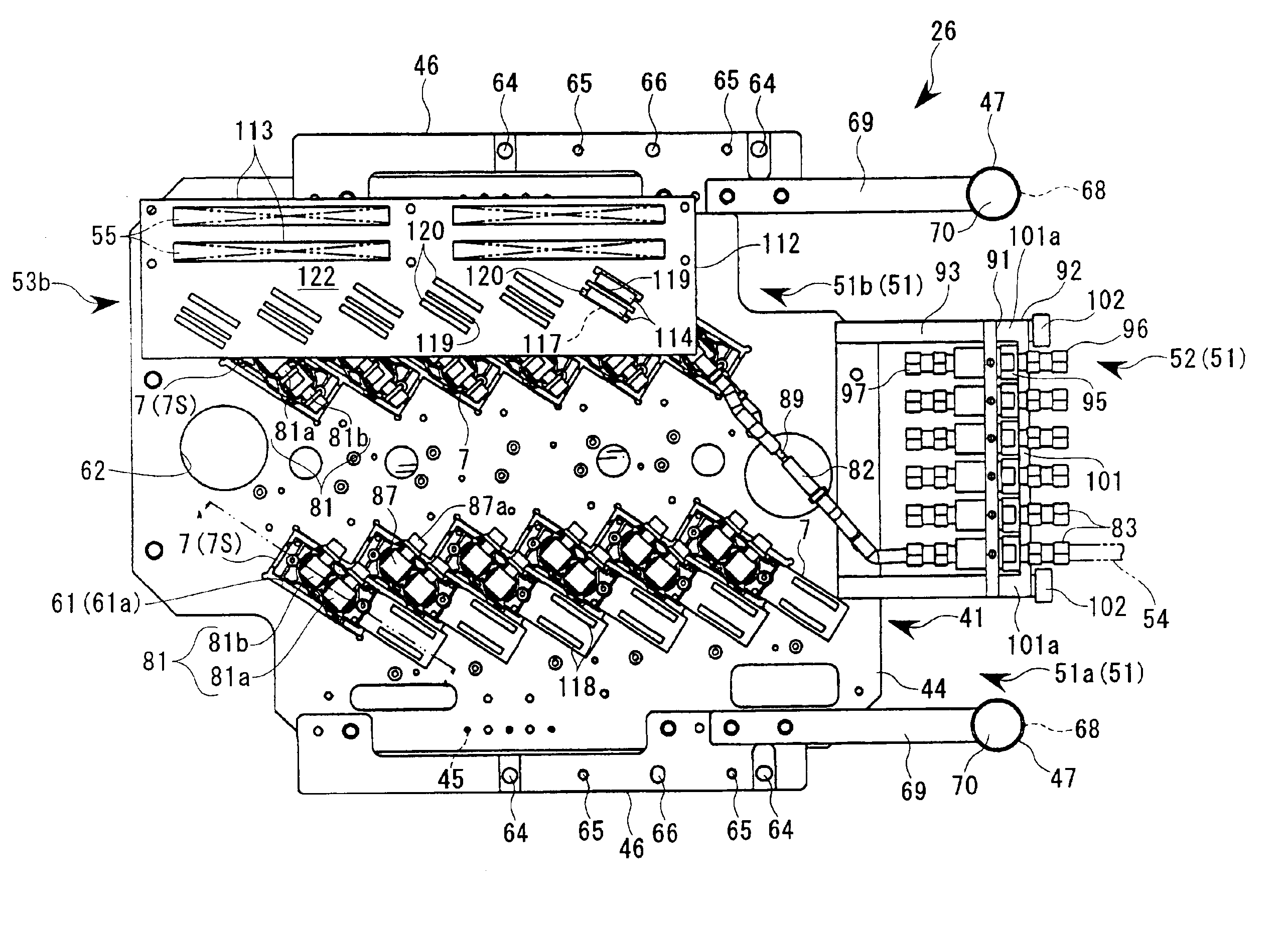
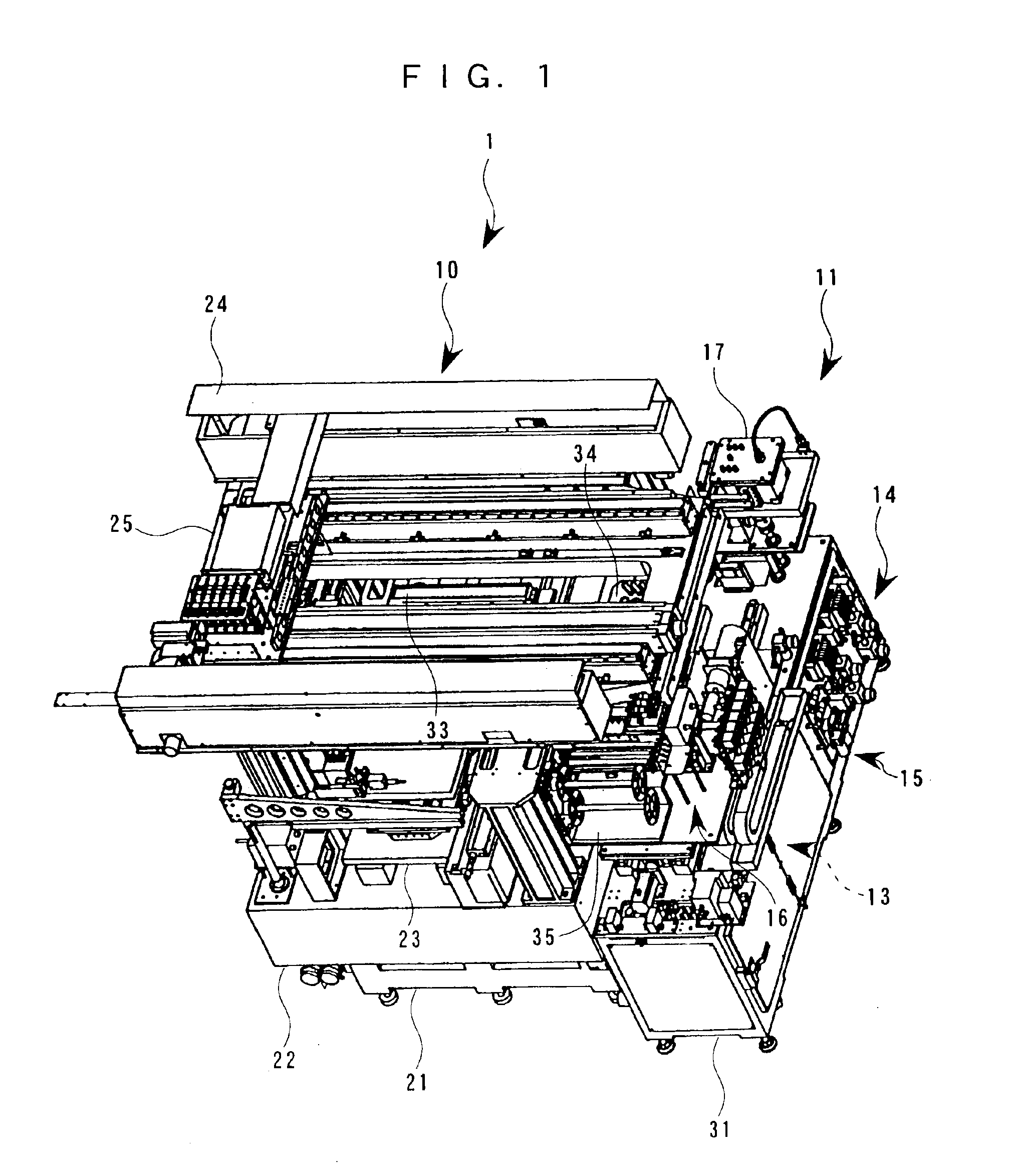
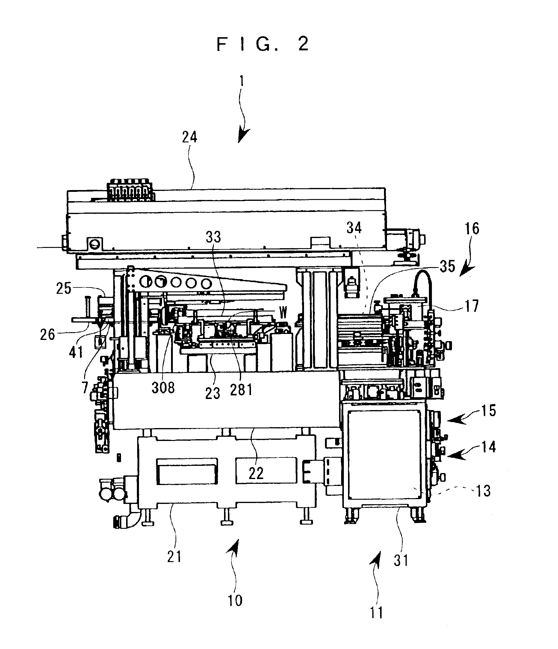
The invention will now be described in detail about the embodiment of this invention with reference to the attached drawings. An ink jet head (functional liquid droplet ejection head) of an ink jet printer is capable of accurately ejecting very small ink droplets in the form of dots, and hence, there is an expectation that the ink jet head can be applied to various fields of manufacturing component parts, e.g., by using special inks, photosensitive or light-emitting resins, etc. as functional liquids (liquids to be ejected). Further, in such an applied technique, a highly viscous functional liquid or the like is expected which have a large influence on the durability of the functional liquid droplet ejection head, and it is necessary that a head unit having a plurality of functional liquid droplet ejection heads accurately integrated in a carriage can be easily mounted on the system or replaced.

A head unit according to this embodiment and a drawing system having the head unit instal...


PUM


Abstract

A head unit for carrying out operations for connecting and disconnecting cables and tubes to and from a plurality of functional liquid droplet ejection heads has a wiring connection assembly carried on a carriage and having a plurality of wiring connectors to be connected to main cables and a plurality of separate cables having one end thereof connected to the respective functional liquid droplet ejection heads and an opposite end thereof connected to the respective wiring connectors, and a piping connection assembly having a plurality of piping joints to be connected to main pipes and a plurality of separate pipes having one end thereof connected to respective functional liquid droplet ejection heads and opposite end thereof connected to respective piping joints.

Description

BACKGROUND OF THE INVENTION1. Field of the InventionThis invention relates to a head unit for carrying on a carriage a plurality of functional liquid droplet ejection heads as represented by ink jet heads and a method of setting the head unit; a drawing system; a method of manufacturing a liquid crystal display device, a method of manufacturing an organic electroluminescence (EL) device, a method of manufacturing an electron emitting device, a method of manufacturing a plasma display panel (PDP) device, a method of manufacturing an electrophoresis display, a method of manufacturing a color filter, and a method of manufacturing an organic EL; a spacer-forming method, a metal wiring-forming method, a lens-forming method, a resist-forming method, and a light diffuser-forming method.2. Description of the Related ArtConventionally, in a large-sized printer or the like, in view of a yield of functional liquid droplet ejection heads, all (one-line) ejection nozzles arranged in the sub-scan...

Claims


Application Information

Patent Timeline
IPC IPC(8): B41J29/02B41J3/407G02B5/20G02F1/01G02F1/1335G02F1/13G02F1/167H01L51/40H01L51/56H01L51/50H01L51/05B41J2/01B05C5/00G02F1/133H01J9/227
CPCB41J3/407B41J29/02G02B5/201G02F1/1303B41J2202/09H01L51/56G02F1/133516G02F1/167H01L51/0004H10K71/13H10K71/00B41J2/01
Inventor OGAWA, MASAHIKO
Owner KATEEVA
Why Eureka
Try Eureka