Slider for slide fastener

a technology of sliding fasteners and sliding plates, applied in the field of sliding plates, can solve the problems of friction resistance between the two, the engagement motion can be unstable, and the fastener elements can be damaged, so as to prevent wear or damage, smooth introduction, and easy operation.

Active Publication Date: 2009-01-22
YKK CORP
View PDF13 Cites 3 Cited by
  • Summary
  • Abstract
  • Description
  • Claims
  • Application Information

AI Technical Summary

Benefits of technology

[0026]According to the second aspect of the invention, the slider is constituted of an upper blade having a pull tab attaching portion and a lower blade located at a position opposing the upper blade and connected thereto through a guide post. The slope-like top surface formed on the intermediate partition is provided on the blade opposing a surface opposite to a surface of the fastener tape in the fastener chain to which the fastener elements are attached. Consequently, the intermediate partition having the slope-like top surface provided within the guide groove of the body of the slider is formed on any one of the upper and lower blades which faces the surface opposite to the surface in which the fastener elements are knitted in or woven in, so as to securely introduce the coupling head of the fastener element.
[0027]According to the third aspect of the invention, the intermediate partition is formed from the rear mouth of the body toward proximal portions on both sides of the guide post. With this configuration, the fastener elements knitted or woven into one side edge of the fastener tape can be securely and smoothly introduced by the intermediate partition provided within the guide groove in the body.
[0028]According to the fourth aspect of the invention, the intermediate partition formed on both sides of the guide post is formed of a raised portion in a narrow width, and the raised portion is disposed in the same direction as the sliding direction of the slider. With this configuration, the intermediate partition provided on both sides of the guide post of the body coincides with a sliding trajectory of the slider, so that the coupling heads of the fastener elements can be guided securely and smoothly.
[0029]According to the fifth aspect of the invention, the intermediate partition provided on both sides of the guide post has a top surface having a fixed width and the top surface is connected to the inner surface through a slope, so that the front surface and the side surface continuous to the top surface of the intermediate partition are connected to the inner surface through the slope. Thus, the coupling heads of the fastener elements exposed from the side edge of the fastener tape are prevented from being worn or damaged due to contact with the intermediate partition, whereby the fastener elements are guided smoothly.
[0030]According to the sixth aspect of the invention, the intermediate partition is provided with a parallel portion in a narrow width whose sides on both sides are parallel at the front end on the rear mouth side, and the parallel portion is formed in a fixed height with respect to the blade. Therefore, the operations of discharging or inserting the fastener elements through the rear mouth in the body of the slider can be carried out smoothly and easily with the coupling heads of the right and left fastener elements coupled with each other by the parallel portion provided within the guide groove.
[0031]According to the seventh aspect of the invention, the intermediate partition is provided such that the width thereof is increased gradually as it goes from the parallel portion toward the raised portion. Thus, the intermediate partition provided within the guide groove is formed such that the width thereof is expanded as it goes from the parallel portion to the raised portion. Thereby, the fastener elements in the fastener chain are engaged and disengaged smoothly and easily. That is, the effects which the present invention exerts are extremely remarkable.

Problems solved by technology

Consequently, when the slider is slid along the fastener elements, frictional resistance between the blade 104 and the fastener chain is increased if the intermediate partition is formed high, and the fastener elements fall in so that the engagement motion sometimes becomes unstable if it is formed low.
Further, because the edge of the intermediate partition is formed in the square shape, the fastener elements can be damaged by the sliding motion when the slider is slid.
Additionally, there is a fear that the sliding operation of the slider cannot be carried out smoothly.
Consequently, it becomes very hard to slide the fastener stringer 224 and the sliding resistance when the slider is slid is increased, and further the fastener elements 223 can damage the coupling heads due to the sliding contact with the slider.

Method used


Image

  • Slider for slide fastener
  • Slider for slide fastener
  • Slider for slide fastener

Examples


first embodiment

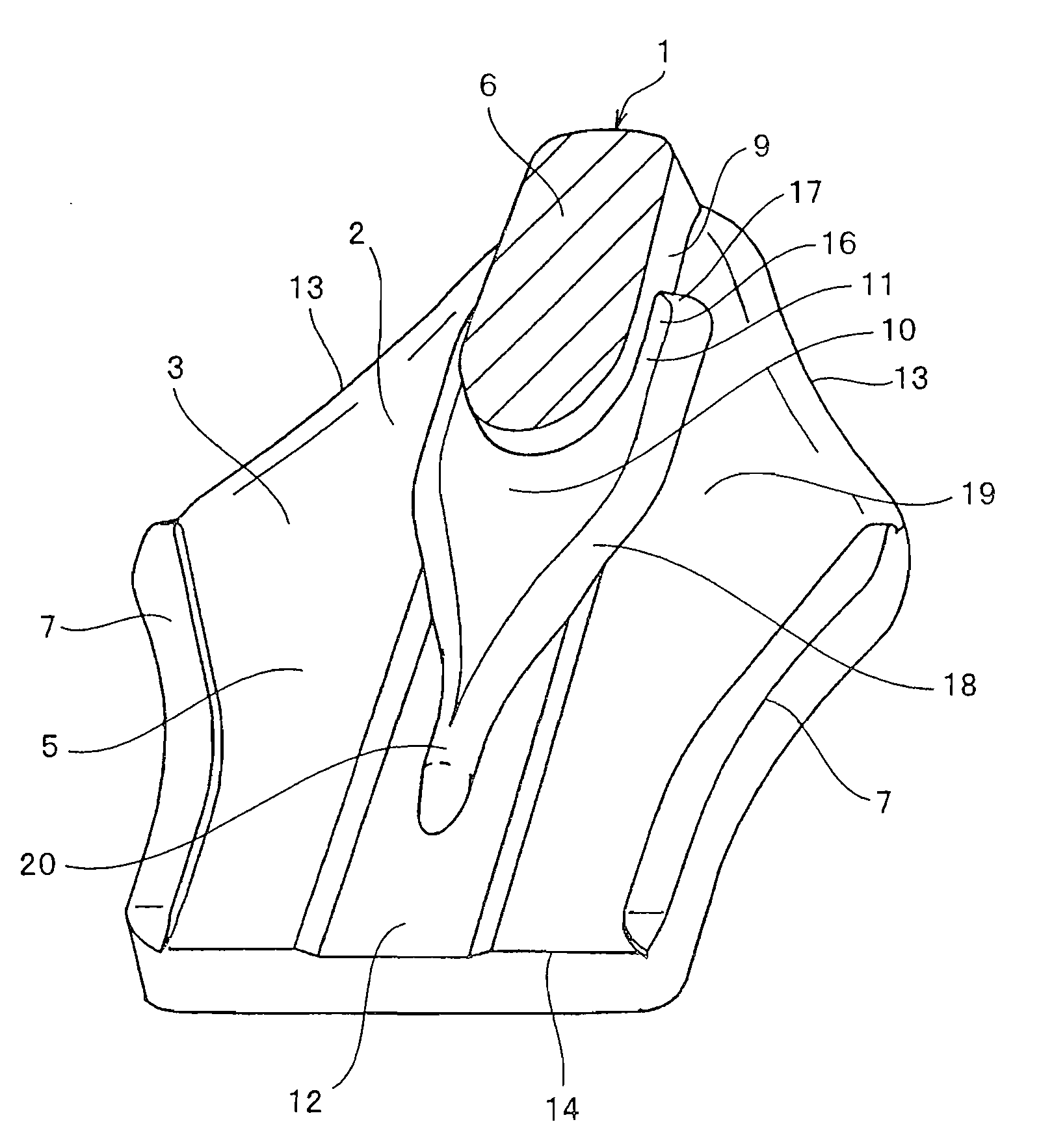
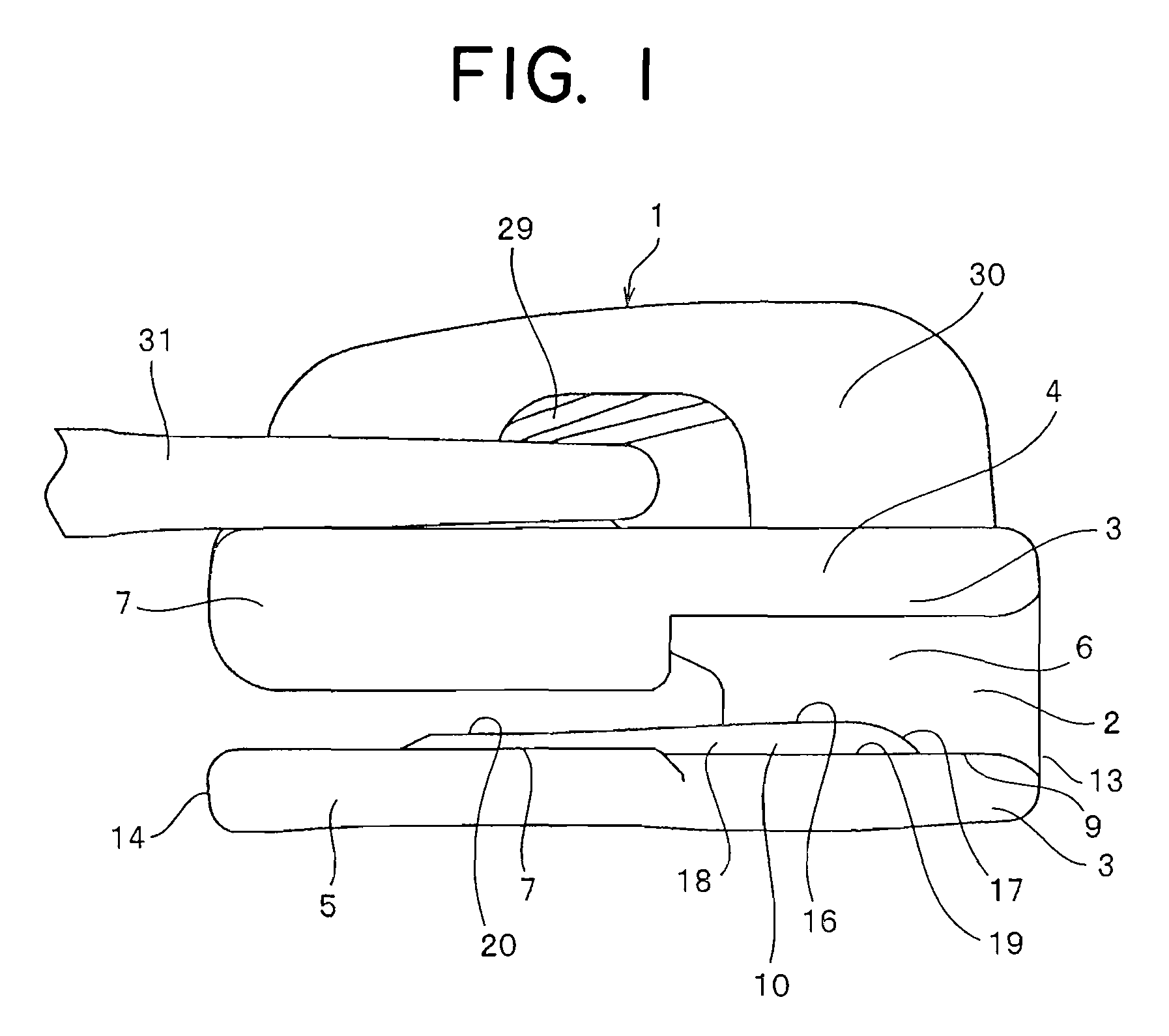
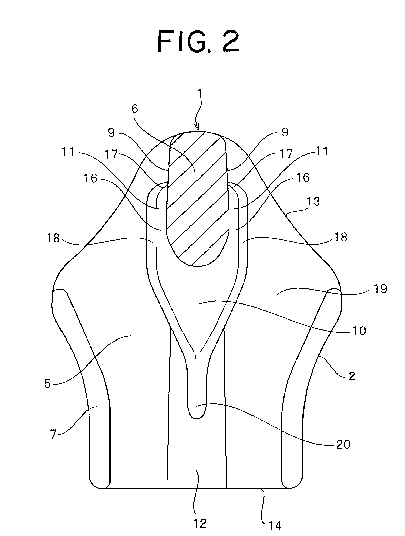
[0055]In a slider for a slide fastener according to a first embodiment shown in FIGS. 1 to 10, a body 2 of a slider 1 is molded by die casting using metal such as aluminum alloy or zinc alloy. In the body 2, an upper blade 4 and a lower blade 5 are combined through a guide post 6, and flanges 7 are provided projectingly on side edges 26 on both sides of the upper blade 4 of the blade 3. A pull tab attaching portion 30 to which a pull tab 31 is attached is provided on the surface of the upper blade 4, and a pawl lever 29 having a locking pawl with automatic locking device is accommodated in the attaching portion 30. The intermediate partition 10 is provided in the center along the longitudinal direction on the inner surface of the upper blade 4 such that the intermediate partition 10 is raised extending from the guide post 6 toward the rear mouth 4 side. A pawl hole 28 in / from which the locking pawl goes / comes is bored in the center of the intermediate partition 10. Of the flange 7 o...

second embodiment

[0061]A slider for a slide fastener according to a second embodiment shown in FIG. 11 handles a so-called back face using slide fastener in which a fastener tape 22 faces an upper blade 4 side while fastener elements 23 are knitted into the back side. Contrary to the first embodiment, the intermediate partition 10 of the lower blade 5 shown in FIGS. 1 to 10 is formed on the upper blade 4. Speaking in detail, the intermediate partition 10 is formed of a top surface 16 whose shoulder mouth 13 side is high while a rear mouth 14 side is low, from both sides halfway of a guide post 6 toward the rear mouth 14 side. A parallel portion 20 is provided at the front end of the intermediate partition 10 so as to be raised inward in a fixed height. The parallel portion 20 is formed in a narrow configuration while its both sides are parallel and the surface thereof is circular, communicating with the intermediate partition 10. A concave groove 12 as wide as the guiding post 6 is provided on both ...

third embodiment

[0062]In a slider for a slide fastener according to a third embodiment shown in FIGS. 12 and 13, an upper blade 4 and a lower blade 5 are connected through a guide post 6 to constitute a body 2 of a slider 1. An intermediate partition 10 is provided on the lower blade 5 such that it extends from an inside end 15 of the guide post 6 toward a rear mouth 14. The intermediate partition 10 is formed of the top surface 16 which is inclined such that a shoulder mouth 13 side is high while the rear mouth 14 side is low. The width of the inside end 15 of the intermediate partition 10 is wider than the width of the guide post 6, so that coupling heads 25 of fastener elements 23 are placed and guided thereby. A parallel portion 20 having parallel both sides is provided at the front end of the intermediate partition 10, so as to exert the same function as the first embodiment. As a modification, as shown in FIG. 14, a beginning portion of the intermediate partition 10 may be moved to the should...


PUM


Abstract

The present invention provides a slider wherein a Y-shaped guide groove which allows a fastener chain to pass therethrough is provided in a body of a slider, the intermediate partition which is raised inward on both sides of a guide post and extends from an inside end of the guide post toward a rear mouth is provided on an inner surface of one of upper and lower blades, and a top surface of the intermediate partition is formed into an entirely inclined slope such that a shoulder mouth side is higher than a rear mouth side, thereby enabling to catch and introduce coupling heads of fastener elements exposed from the side edges of the fastener tapes, so that the coupling heads of the right and left fastener elements are engaged with each other between the guide post and the rear mouth.

Description

BACKGROUND OF THE INVENTION[0001]1. Field of the Invention[0002]The present invention relates to a slider of a linear slide fastener, and more specifically, to a slider for a slide fastener which is applicable to a fastener chain in which linear fastener elements formed into a coil shape or zigzag shape are attached to one side edge of a fastener tape, particularly, a flat thin linear slide fastener chain having no core thread, in which fastener elements are knitted or woven so that a coupling head side of the fastener elements is exposed from a fastener tape.[0003]2. Description of the Related Art[0004]There is conventionally known a slide fastener slider, as shown in FIG. 17, having the following configuration. Raised portions 111 which are raised in a fixed height from an upper blade 104 are provided on proximal portions on both sides of a guide post 106 of an inner surface of the upper blade 104 of a slider body. A front end portion whose tip is pointed toward a rear mouth side ...

Claims


Application Information

Patent Timeline
Patent Type & Authority Applications(United States)
IPC IPC(8): A44B19/26A44B19/24
CPCA44B19/26Y10T24/2582Y10T24/2598Y10T24/2514Y10T24/2511Y10T24/2561Y10T24/2586Y10T24/2584
Inventor MIYAZAKI, YOHEIKEYAKI, KEIICHI
Owner YKK CORP
Why Eureka
Try Eureka