Blood analysis device and blood analysis method

a technology of blood analysis and blood, which is applied in the direction of specific gravity measurement, laboratory glassware, instruments, etc., can solve the problems of fluctuation of the concentration of measured chemical substances and the cost of the device, and achieve the effect of smooth introduction

Inactive Publication Date: 2009-09-01
JAPAN SCI & TECH CORP
View PDF8 Cites 10 Cited by
  • Summary
  • Abstract
  • Description
  • Claims
  • Application Information

AI Technical Summary

Benefits of technology

[0023]That is, in the blood analysis device of the present invention, a centrifugal operation in two different directions is possible, and the calibrator solution in the calibrator solution introducing channel is conveyed to the plasma separating section (referred to also as a sensor section in the description) by the centrifugal operation in the first centrifugal direction. After sensor calibration, the substrate is centrifuged in the second centrifugal direction, and the calibrator solution can be reliably discharged from the plasma separating section (sensor section). After the calibrator solution discharge, centrifuging is effected again in the first centrifugal direction, thereby conveying the blood in the blood introducing channel to the plasma separating section (sensor section) and effecting separation of blood cells and plasma.
[0027]When a blood collecting needle is attachable to a blood intake port of the blood introducing channel in the substrate, whole blood collected via the blood collecting needle can be introduced directly into the blood reservoir. When the blood reservoir and the blood introducing channel are subjected to a hydrophilic treatment beforehand, the blood sample can be smoothly introduced.

Problems solved by technology

For this purpose, a position sensor for the liquid has to be newly installed in the inside or the outside of the blood analysis device, and there has been a problem that the device becomes expensive because such control mechanism or position sensor is added.
Accordingly, even when the amount of the calibrator solution remaining on the surface of the flow channel or analysis means is small, the analysis device having a less amount of introduced plasma has a problem that the measured concentrations of the chemical substances are fluctuated.

Method used


Image

  • Blood analysis device and blood analysis method
  • Blood analysis device and blood analysis method
  • Blood analysis device and blood analysis method

Examples


first embodiment

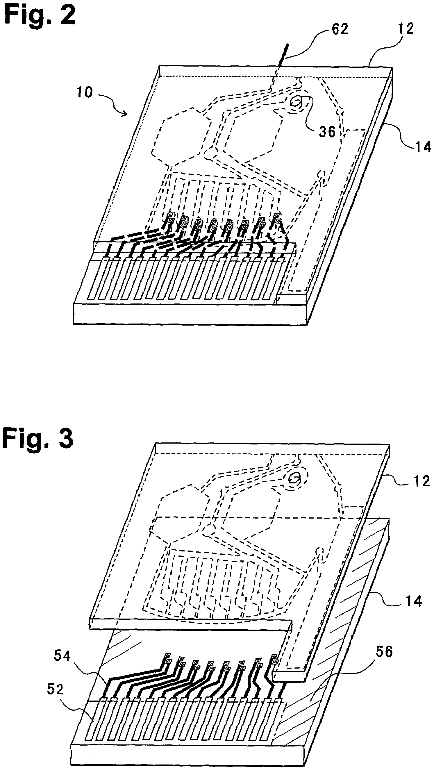
[0056]FIG. 2 is a perspective view of a blood analysis device according to a first embodiment of the present invention, FIG. 3 is an exploded perspective view, FIG. 4 is a bottom plan view of an upper substrate, and FIG. 5 is a plan view of a lower substrate. In these figures, reference numeral 10 denotes a blood analysis device, and an upper substrate 12 is overlaid on a lower substrate 14. The upper and lower substrates 12, 14 are, for example, made of resins such as polyethylene terephthalate (PET) and polycarbonate (PC).

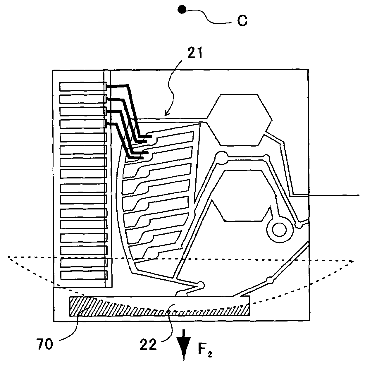
[0057]In a bottom surface of the upper substrate 12, as shown in FIG. 4, a calibrator solution reservoir 16 and a blood reservoir 18 are provided slightly nearer an upper side of the figure, a plasma separating section (sensor section) 21 is disposed beneath, and a calibrator solution waste reservoir 22 is laterally disposed. The plasma separating section (sensor section) 21 is provided with a plurality of sensor grooves 20, and each sensor groove 20 has an enlar...

second embodiment

[0078]FIG. 16 shows a blood analysis device according to a second embodiment of the present invention. This analysis device 10 is different from the first embodiment in that, as shown by slant lines in the figure, inner walls of a blood reservoir 18, an upstream blood introducing channel 24b, and an inlet port 40, and channel inner walls of a through hole 36 to a calibrator solution reservoir 16 are subjected to a hydrophilic treatment. Instead of a blood collecting needle, a blood collecting cylinder 76 is attached to the blood intake port 40. Another structure is the same as that of the first embodiment.

[0079]In the blood analysis device of the first embodiment, blood and calibrator solution can be conveyed utilizing a centrifugal force, but suction using a pump is required for collecting the blood from a person being tested. The second embodiment uses a capillary blood sampling device 76 for use in a blood sugar (glucose) value inspection performed by each person at home at prese...

example 1

[0084]A blood analysis device as shown in FIGS. 2, 3, was prepared and attempts were made to perform calibration of an electrochemical sensor, introduction of blood, separation of blood cells and plasma by centrifuge, and analysis of various chemical substance concentrations in plasma. Procedures of the device preparation have been substantially already described. In the blood analysis device used herein, a PET resin was used in a substrate, and a size thereof was a 20 mm square.

[0085]As to sensor electrodes, in FIG. 8, the respective sensor electrodes were disposed for analyzing glucose, pH, lactic acid, creatinine, sodium ion, potassium ion, calcium ion, and blood urea nitrogen (BUN) from left side in FIG. 8. As a calibrator solution, Dulbecco's phosphate buffer (PBS, 153.2 mM NaCl, 4.15 mM KCl, pH 7.4) was used with supplement of 1.0 mM CaCl2,4.0 mM glucose, 5.0 mM urea, 1.0 mM lactic acid, and 100 μM creatinine.

[0086]After introducing about 1 μL of calibrator solution into a cal...


PUM

PropertyMeasurementUnit
depthaaaaaaaaaa
thicknessaaaaaaaaaa
thicknessaaaaaaaaaa

Abstract

A blood analysis device for centrifugally separating plasma in a channel, wherein conveyance of blood, plasma and calibration liquid is effected within the device without using a pump or the like. The calibrator solution is reliably discharged from a sensor portion so as to make high precision analysis possible. A sensor section is provided in a plasma separating section and disposed on the side associated with a first centrifugal pressing direction as seen from a blood reservoir and a calibrator solution reservoir, while a calibrator solution waste reservoir is disposed in a second centrifugal pressing direction as seen from the plasma separating section (sensor section). The calibrator solution is conveyed to the sensor section by centrifugal operation in the first centrifugal direction. After sensor calibration, the calibrator solution can be reliably discharged from the sensor section by effecting centrifuging in the second centrifugal direction. After the calibrator solution discharge, centrifuging is effected again in the first centrifugal direction, thereby conveying the blood in the blood reservoir to the sensor section and effecting separation of blood cells and plasma. In the case of providing a plurality of sensors, a blood introducing channel from the blood reservoir is branched downwardly of a sensor groove for communication, with the blood cells being fractionated in the branch section. The individual sensors can be isolated from each other by blood cell fraction, making higher precision analysis possible.

Description

[0001]This is a National Stage application under 35 U.S.C. § 371 of PCT / JP2004 / 001802 filed on Feb. 18, 2004, which claims priority from Japanese patent application 2003-040481 filed on Feb. 19, 2003, all of which are incorporated herein by reference.TECHNICAL FIELD[0002]The present invention relates to a chip-shaped blood analysis device constituted by micro trench channels formed in an insulating substrate such as a quartz plate or a polymer resin plate. Particularly, the present invention relates to a channel structure for conveying liquids such as a calibrator solution for an analysis sensor and blood by a centrifugal force, when a small amount (several μL or less) of blood is introduced into trench channels on the chip, centrifugal separation is carried out to separate the blood into a blood cell and a plasma, and concentrations of various chemical material in the plasma are then measured.BACKGROUND ART[0003]In a conventional medical check-up or diagnosis of a disease state, se...

Claims


Application Information

Patent Timeline
Patent Type & Authority Patents(United States)
IPC IPC(8): G01N33/72C12M1/34C12Q1/00B01L3/00G01N33/49
CPCB01L3/502753G01N33/491B01L2200/10B01L2200/148B01L2300/0816B01L2300/0861B01L2400/0409B01L2300/0645
Inventor OGAWA, HIROKIHORIIKE, YASUHIRO
Owner JAPAN SCI & TECH CORP
Why Eureka
Try Eureka