Composite profile and method for manufacturing the composite profile

a composite profile and composite technology, applied in the field of composite profiles, can solve the problems of undulation on the surface of the covering profile, disadvantage of the conductor rail, etc., and achieve the effect of reducing the height toleran

Active Publication Date: 2010-05-11
CONSTELLIUM SWITZERLAND
View PDF8 Cites 4 Cited by
  • Summary
  • Abstract
  • Description
  • Claims
  • Application Information

AI Technical Summary

Benefits of technology

[0018]In this connection it should be pointed out that the insert rods formed from steel are modified in such a way that lateral welding penetrates through to the light metal of the carrier profile. Due to welding through to the aluminium, the following advantages amongst others arise:
[0027]The requirement is a maximum possible width of the sliding surface with the possibility of spreading from the side and mechanical anchoring which, even with completely worn wear profiles, ensures anchoring of the remaining sliding surfaces of which there are then two. Also, a reduction of the fitted height tolerances compared with known composite profiles is desired. The possibility of local manufacture worldwide is desirable too, without having to upgrade a large light metal extruder.

Problems solved by technology

Conductor rails of which the wear components are attached to the live carrier profile by screws or additional inserts passing through them laterally, also proved to be disadvantageous.
Other known manufacturing methods can disadvantageously lead to undulations on the surface of the covering profile, caused by caulking or stamping the carrier profile in stages.

Method used


Image

  • Composite profile and method for manufacturing the composite profile
  • Composite profile and method for manufacturing the composite profile
  • Composite profile and method for manufacturing the composite profile

Examples


Embodiment Construction

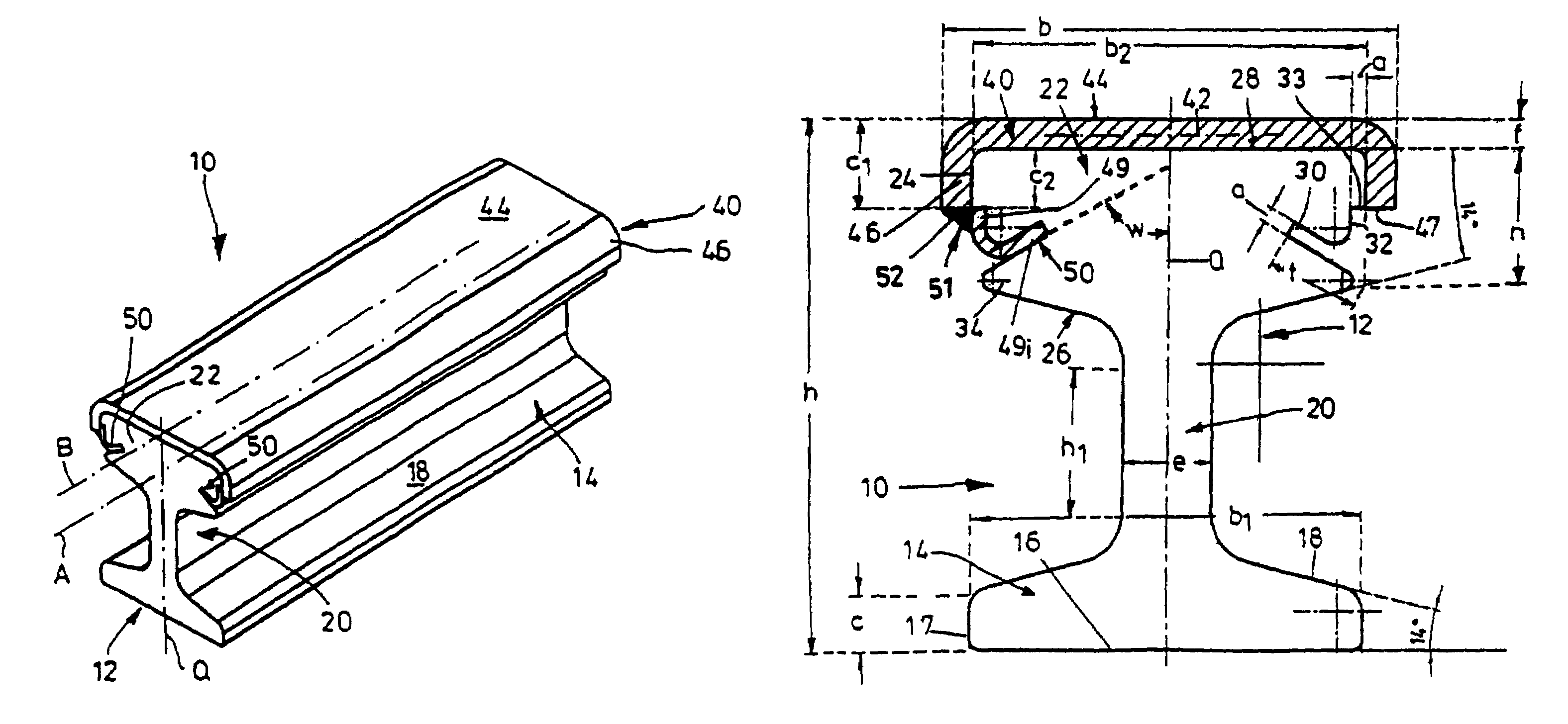
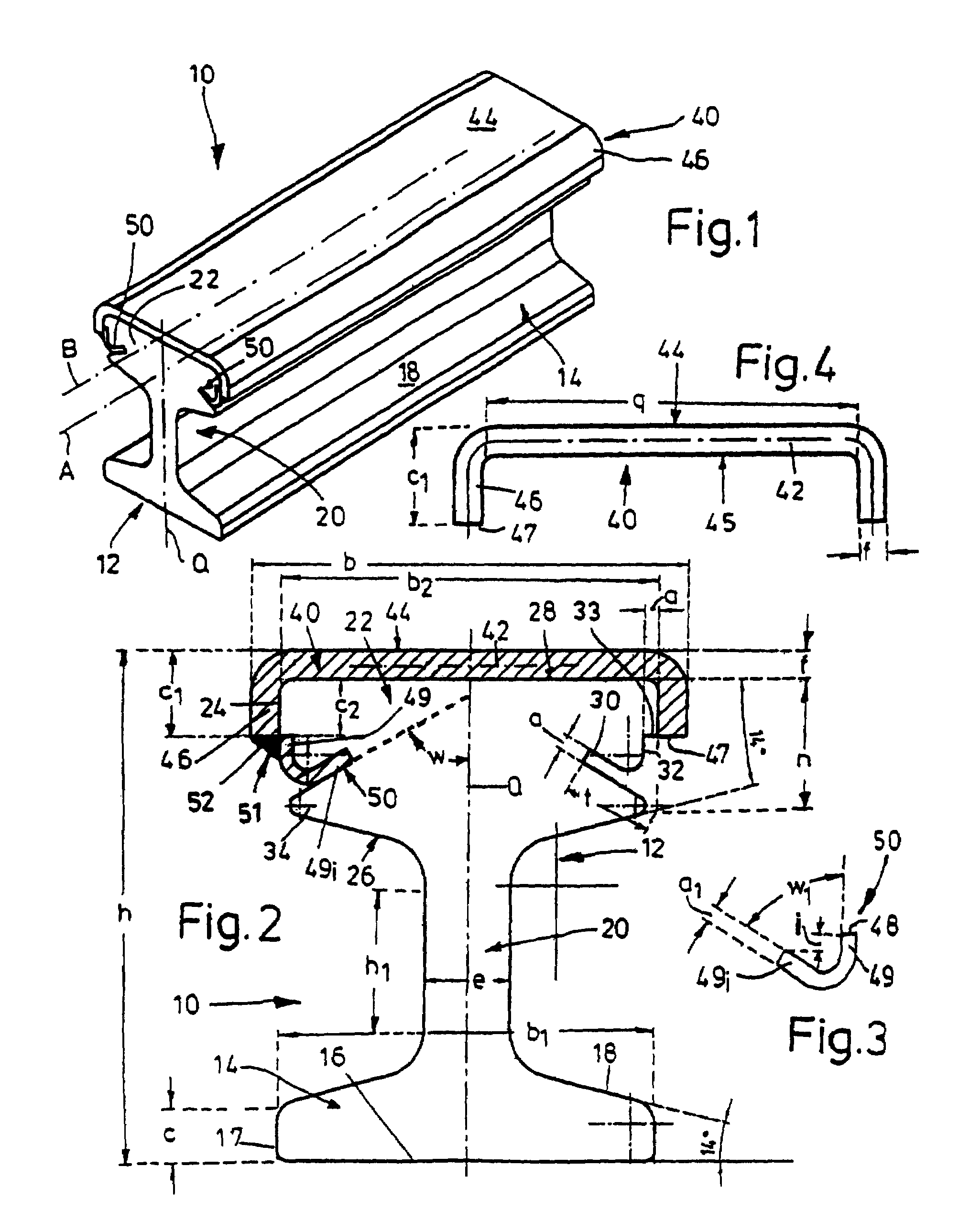
[0039]A composite profile 10 with a height h of 105 mm here and a maximum width b of 92 mm according to FIG. 1 comprises a rail-like carrier profile 12 having a rail foot 14 and a continuous rail head 22 formed integrally on the latter by means of a rail web 20. Two longitudinal edges 17 with a height c of 10 mm defining the foot surface 16 of the rail foot 14 run parallel to each other at a distance b1 of 80 mm here.

[0040]From these longitudinal edges 17, the two ridge surfaces 18 of the rail foot 14, which are somewhat inclined towards them, are inclined slightly upwards to the cross-sectional centre axis Q crossing the longitudinal axis A of the composite profile 10, and merge with that axial rail web 20 with a height h1 of approximately 30 mm and a thickness e of approximately 18 mm. Adjoining the upper end of the rail web 20 are the lower surface 26 which extends to the longitudinal edges 24 of the rail head 22 and of which the width b2 measures approximately 78 mm and of which...


PUM


Abstract

A composite profile comprising an extruded aluminum alloy carrier profile comprising a rail head having a longitudinal axis B, the rail head comprises a surface and two longitudinal edges extending parallel to the longitudinal axis B and a metal channel shaped profile strip comprising a base portion spanning the surface of the rail head and parallel side legs which lie on the longitudinal edges of the head rail, an insert rod is provided on the parallel side legs which lie on the longitudinal edges of the head rail and engage in lateral slots provided in the two longitudinal edges of the rail head, wherein the profile strip is attached to the carrier profile under mechanical pretension by way of a weld seam which contacts the rail head of the extruded aluminum alloy carrier profile.

Description

CROSS REFERENCE TO RELATED APPLICATIONS[0001]This application is related to U.S. application Ser. No. 11 / 708,210 filed Feb. 20, 2007 and U.S. application Ser. No. 11 / 815,018 filed Jul. 30, 2007.BACKGROUND OF THE INVENTION[0002]The invention concerns a composite profile having a rail-like carrier profile extruded from light metal material as well as a profile strip made of a harder metal and resting on its top surface. The invention covers a method for manufacturing such a composite profile.[0003]DE 24 32 541 A1 shows a method for manufacturing conductor rails from a carrier profile and at least one overlay which forms at least part of the surface of the carrier profile serving as the conductor and which consists of a profile strip of a different metal to the covering profile having high abrasion resistance. The free cross-sectional ends of the flat profile strip are formed by edge surfaces which are inclined towards each other and which in the fitted position fit snugly against corr...

Claims


Application Information

Patent Timeline
Patent Type & Authority Patents(United States)
IPC IPC(8): B60M1/00
CPCB60M1/302
Inventor WOMPNER, DIETHELMNETZEL, TIMO
Owner CONSTELLIUM SWITZERLAND
Why Eureka
Try Eureka