

Endoscopic treatment instrument
a treatment instrument and endoscope technology, applied in the field of endoscope treatment instruments, can solve the problems of inability to hold inability to achieve the effect of increasing the energy density of the object to be treated
- Summary
- Abstract
- Description
- Claims
- Application Information
AI Technical Summary
Benefits of technology
Problems solved by technology
Method used
Image

Examples
first embodiment
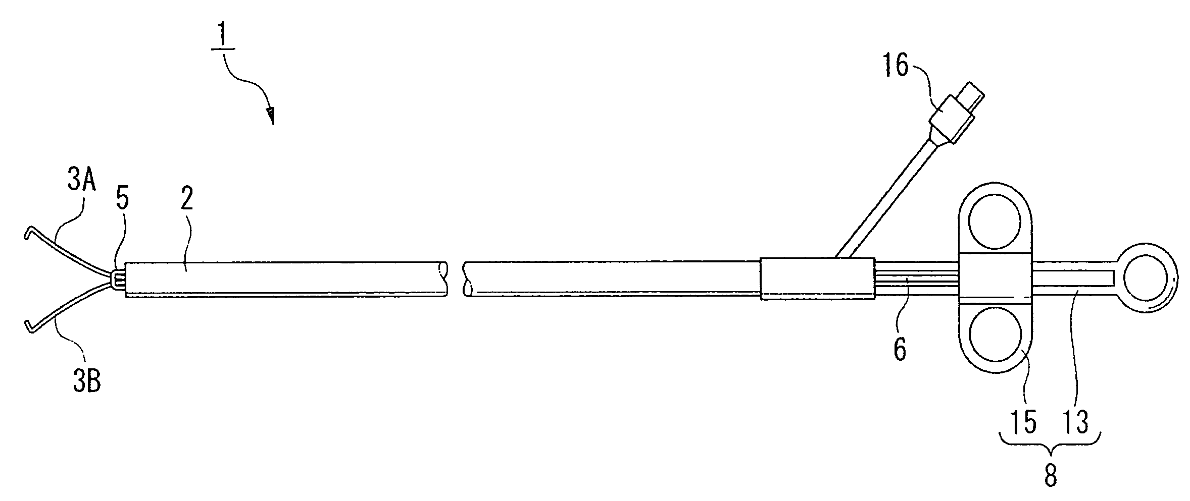
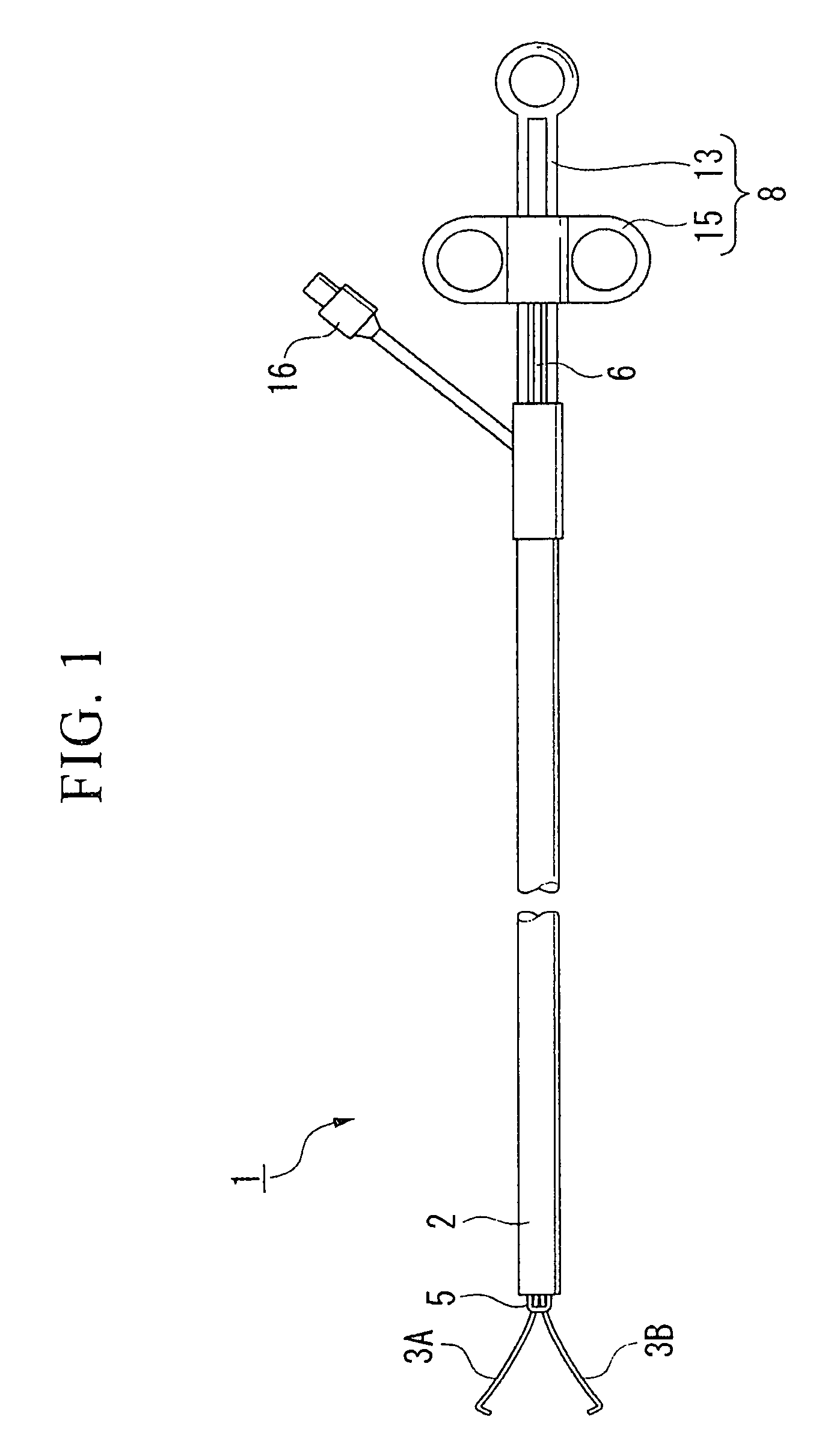
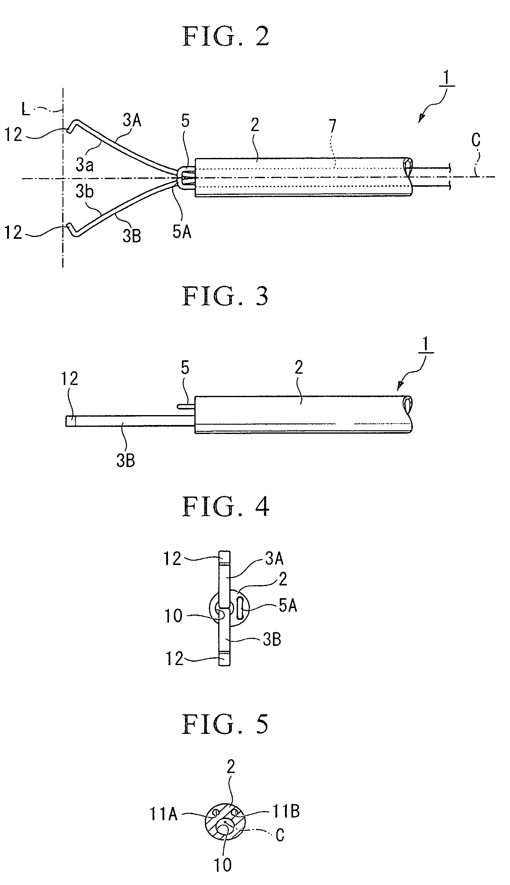
[0038]With reference to FIGS. 1 to 10, a description will be given of a first embodiment according to the present invention. As illustrated in FIGS. 1 to 4, a forked (two-pronged) cutting forceps (endoscopic treatment instrument) 1 is provided with a sheath 2 having electrical insulation properties, with a pair of arm portions 3A and 3B which are disposed opposite to each other, which protrude and retract with respect to the sheath 2, and which open and close to thereby hold an object to be treated (or untreated object), with a cutting electrode (energy treating portion) 5 which protrudes from and is fixed to the distal end of the sheath 2 and which supplies a high-frequency electric current (predetermined energy) to an untreated object when it comes in contact with the untreated object, with a control wire (extension and retraction force transmitting portion) 6 which transmits to the pair of the arm portions 3A and 3B extension and retraction force with respect to the sheath 2 to o...
third embodiment
[0054]Next, a description will be given of an operation of the forked cutting forceps 30 when used in a polyp P extracting operation as one example.
[0055]Firstly, an insertion section of the endoscope (not illustrated) is positioned in the vicinity of a polyp P and thereafter, the sheath 32 of the forked cutting forceps 30 protrudes from the insertion section of the endoscope. Then, the first electrode terminal 37 and the second electrode terminal 38 are connected to the high-frequency power supply, and thereafter, the control wire 6 is moved toward the distal end side of the sheath 32 and the pair of the arm portions 31A and 31B is expanded or opened.
[0056]Subsequently, the arm portions 31A and 31B are positioned so as to sandwich the polyp P, and then, the control wire 6 is moved toward the proximal end of the sheath 32. At this time, the pair of the arm portions 31A and 31B is pulled or drawn in the sheath 32 so that the polyp P is encircled and held by opposing surfaces 31a and...
fourth embodiment
[0062]Next, a description will be given of an operation of the forked cutting forceps 40 when used in a polyp P extracting operation as one example.
[0063]Firstly, an insertion section of the endoscope (not illustrated) is positioned in the vicinity of the polyp P, and thereafter, the sheath 2 protrudes from the insertion section of the endoscope. Then, the first electrode terminal 45 and the second electrode terminal 47 are connected to the high-frequency power supply, and thereafter, the control wire 42 is moved toward the distal end side of the sheath 2 and the pair of the arm portions 41A and 41B is expanded or opened.
[0064]Subsequently, the arm portions 41A and 41B are positioned so as to sandwich the polyp P, and then, the control wire 42 is moved toward the proximal end of the sheath 2. At this time, the pair of the arm portions 41A and 41B is pulled or drawn in the sheath 2 so that the polyp P is enclosed and held by opposing surfaces 41a and 41b and the hooked portions 12.
[...
PUM
 Abstract
Description
Claims
Application Information