Axial transfer line degassing

a transfer line and fluid technology, applied in the direction of instruments, separation processes, membranes, etc., can solve the problems of inability to achieve accurate and sensitive results, unwanted modifications or deterioration of chromatographic fluids, and traditional techniques generally falling short of the desired degree of separation efficiency, etc., to achieve the effect of easily manipulating into the desired configuration

Inactive Publication Date: 2010-05-11
IDEX HEALTH & SCI
View PDF80 Cites 26 Cited by
  • Summary
  • Abstract
  • Description
  • Claims
  • Application Information

AI Technical Summary

Benefits of technology

[0016]Another embodiment of the invention provides for a method for treating a fluid involving a transfer line apparatus having an outer member defining a first chamber having a length, an inlet, and an outlet, with the outer member being substantially gas and liquid impermeable. The apparatus further includes a primarily non-porous inner barrier extending within the outer member and at least partially along the first chamber, with the inner barrier being substantially gas-permeable and liquid-impermeable. The inner barrier defines a second chamber by being interposed between the second chamber and the first chamber. The second chamber has an open end and a substantially opposed closed end. The method further provides for operably coupling the open end of the second chamber into communication with a vacuum source so as to substantially evacuate the second chamber. The fluid is transported through the first chamber from the inlet through the outlet so as to effect a vacuum degassing or regassing prevention operation on the fluid.

Problems solved by technology

A prime example of such an application relates to the fluids utilized in liquid chromatography where the presence of even small amounts of dissolved gases interferes with the accuracy and sensitivity of the results obtained.
In situations where the dissolved gases are chemically active, unwanted modifications or deterioration in the chromatographic fluids can occur.
As conventionally applied, however, these traditional techniques have generally fallen short of the desired degree of separation efficiency.

Method used


Image

  • Axial transfer line degassing
  • Axial transfer line degassing
  • Axial transfer line degassing

Examples


Embodiment Construction

[0028]The objects and advantages enumerated above together with other objects, features, and advances represented by the present invention will now be presented in terms of detailed embodiments described with reference to the attached drawing figures which are intended to be representative of various possible configurations of the invention. Other embodiments and aspects of the invention are recognized as being within the grasp of those having ordinary skill in the art.

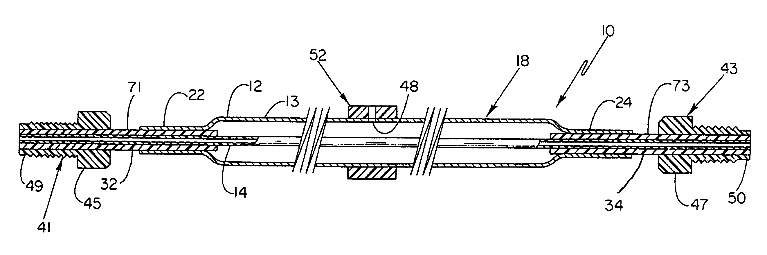
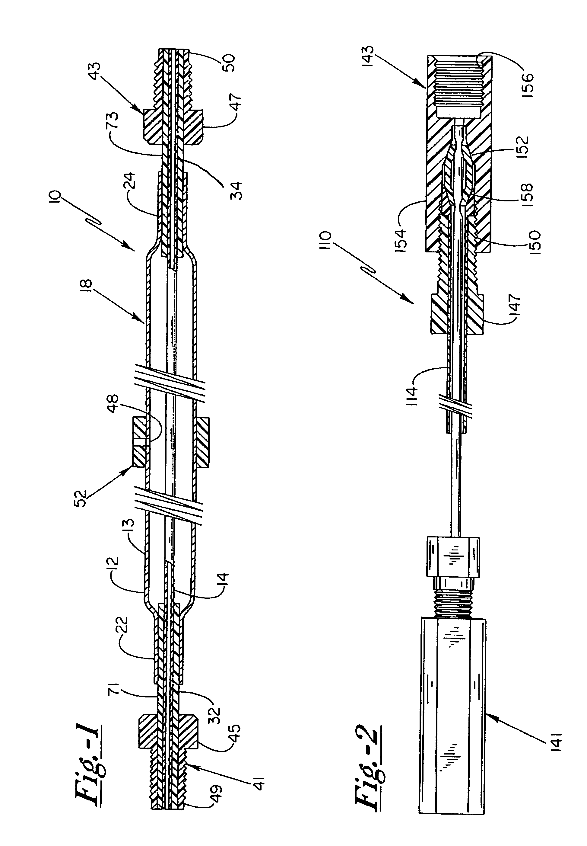
[0029]With reference now to the drawings, and first to FIG. 1, a transfer line degassing apparatus 10 of the present invention includes an outer tube 12 and an inner tube 14 disposed within outer tube 12. Outer tube 12 preferably forms an elongated sealed chamber through which inner tube 14 extends.

[0030]As illustrated in FIG. 1, outer tube 12 includes an inlet end 22 and an outlet end 24, with inner tube 14 having a corresponding inlet portion 32 and outlet portion 34. Inlet and outlet connection devices 41, 43 are p...


PUM

PropertyMeasurementUnit
thicknessesaaaaaaaaaa
diameteraaaaaaaaaa
flexibleaaaaaaaaaa

Abstract

An elongated flow-through degassing apparatus includes an elongated gas and liquid impermeable outer member and a gas-permeable, liquid-impermeable inner barrier extending within the outer member and at least partially along a first chamber defined within the outer member. The apparatus also includes inlet and outlet connection structures operably coupled to respective portions of the outer member and a second chamber defined by the inner barrier to further enable a sealed engagement between the outer member and the inner barrier, and to provide for connection devices to operably couple the degassing apparatus of the present invention to respective spaced apart components. The degassing apparatus may be sufficiently flexible so as to be readily manipulatable into desired configurations.

Description

CROSS-REFERENCE TO RELATED APPLICATIONS[0001]This application is a continuation-in-part of U.S. patent application Ser. No. 10 / 981,934, now U.S. Pat. No. 7,144,443, filed on Nov. 5, 2004 and entitled “Axial Transfer Line Degassing”, which itself is a continuation-in-part of U.S. patent application Ser. No. 10 / 702,013, now U.S. Pat. No. 6,949,132, filed on Nov. 5, 2003 and entitled “Axial Degassing Transfer Lines”, the contents of which are incorporated herein in their entirety.FIELD OF THE INVENTION[0002]The present invention relates generally to systems for degassing fluids utilized in a wide variety of applications, including the degassing of chromatographic fluids, inks, semiconductor processing fluids, beverages, and laboratory-grade fluids, and more particularly to a flow-through transfer line degassing apparatus wherein transfer lines extending between respective components in systems incorporating such an apparatus simultaneously act to operably degas fluids passing therethro...

Claims


Application Information

Patent Timeline
Patent Type & Authority Patents(United States)
IPC IPC(8): B01D19/00B01D53/22
CPCB01D19/0031B01D19/0036B01D63/06B01D53/22B01D2313/13
Inventor GERNER, YURISIMS, CARL W.THIELEN, THOMAS J.
Owner IDEX HEALTH & SCI
Why Eureka
Try Eureka