Magnetizing method, and motor and method of manufacturing motor

a technology of magnetization pattern and manufacturing method, which is applied in the direction of magnets, mechanical energy handling, magnetic bodies, etc., can solve the problems of reducing the printing performance of lbp, impaired ability of optical disc drives to read and write information from and on optical discs, etc., and achieves the effect of preventing the occurrence of undesired vibration of the motor and facilitating the optimization of the magnetization pattern

Inactive Publication Date: 2010-05-11
ALPHANA TECH CO LTD
View PDF8 Cites 0 Cited by
  • Summary
  • Abstract
  • Description
  • Claims
  • Application Information

AI Technical Summary

Benefits of technology

[0021]This invention has the following advantages. It is possible to easily implement an optimization of a magnetization pattern given to a raw member for a magnet. In this invention, a boundary between magnetic poles on a ring-shaped magnet in a motor extends on a straight line out of the center of the ring. Thereby, it is possible to prevent the occurrence of undesired vibration of the motor.

Problems solved by technology

In the event that the rotor of a motor in an optical disc drive develops a whirl (an undesirable deflection) due to unsteady support of the rotary shaft of the motor or floats in a direction of slipping out of a related bearing during operation of the motor, the ability of the optical disc drive to read and write information from and on an optical disc is impaired.
When a motor in an LBP has a similar problem, the printing performance of the LBP is decreased.

Method used


Image

  • Magnetizing method, and motor and method of manufacturing motor
  • Magnetizing method, and motor and method of manufacturing motor
  • Magnetizing method, and motor and method of manufacturing motor

Examples


first embodiment

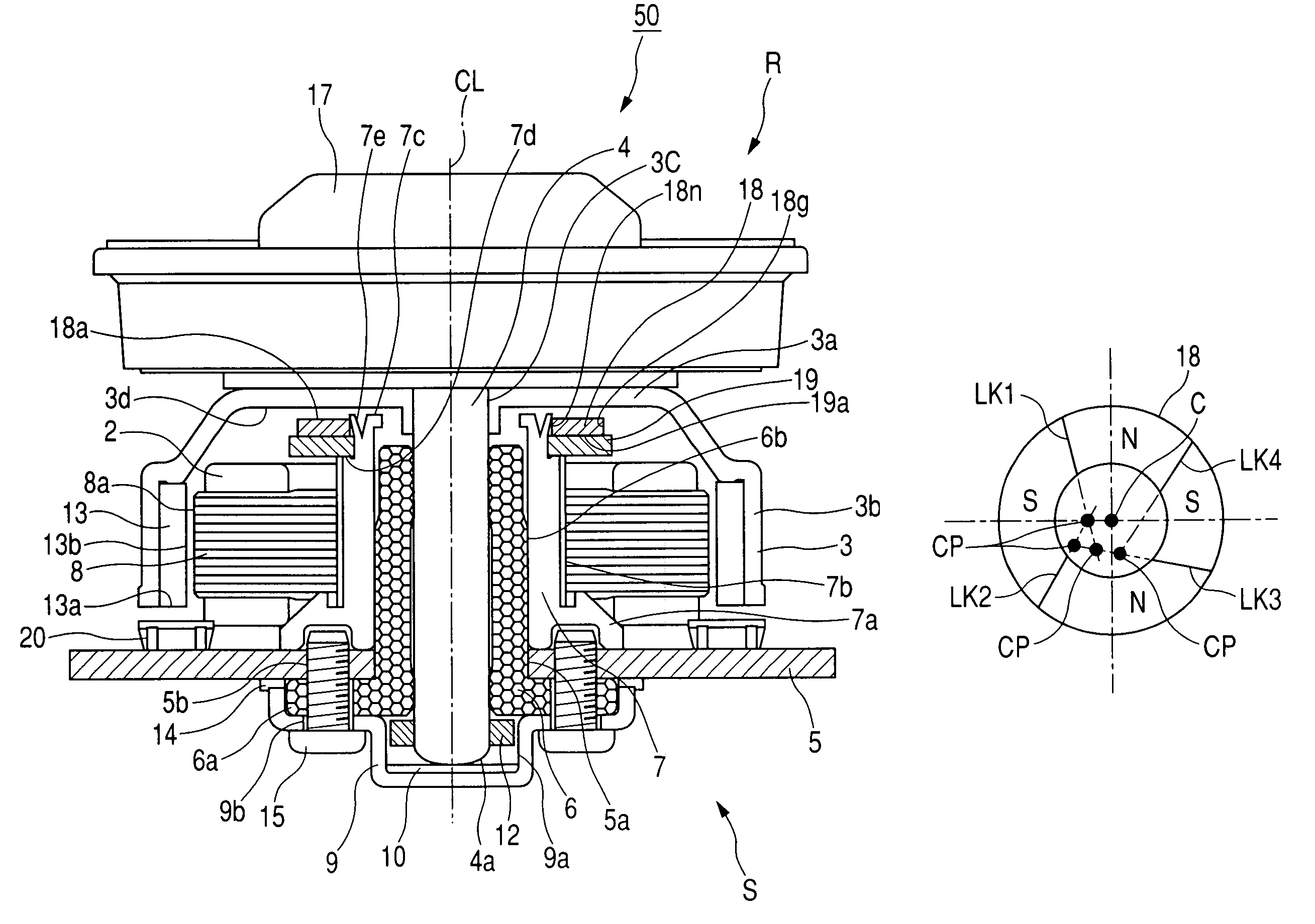
[0044]FIG. 1 shows a motor 50 according to a first embodiment of this invention. The motor 50 is designed to drive, for example, an optical disc. As shown in FIG. 1, the motor 50 has a rotor R and a stator S. The rotor R is rotatably supported on the stator S. The motor 50 has an axis CL coincident with a rotation axis about which the rotor R can rotate.

[0045]The rotor R has a disc-shaped or cylindrical body, and a spindle 4 fixed to the rotor body and being coaxial with the axis CL. The spindle 4 is rotatably supported by bearings including a radial bearing 6 taking the shape of a sleeve. The radial bearing 6 is provided between the spindle 4 and the stator S. The spindle 4 coaxially extends through the radial bearing 6.

[0046]The stator S includes a motor base 5, the radial bearing 6, a bearing holder 7, and a core 8. The radial bearing 6 is fixed to the motor base 5. The bearing holder 7 substantially has the shape of a sleeve. The radial bearing 6 coaxially fits into the bearing ...

second embodiment

[0101]A motor in a second embodiment of this invention is similar to that in the first embodiment thereof except that the bias magnet 18 is fixed to the rotor R rather than the stator S. Specifically, the bias magnet 18 is fixed to, for example, the rotor yoke 3. The core 8 or the back yoke 19 in the stator S is opposed to the bias magnet 18 so that an attractive force will be developed therebetween. Thus, the major part of the rotor R is attracted toward the stator S.


PUM

PropertyMeasurementUnit
diameteraaaaaaaaaa
diameteraaaaaaaaaa
rotation characteristicsaaaaaaaaaa

Abstract

A motor includes a stator and a rotor. The rotor is relative to the stator, and has a rotation axis. A magnet and a magnetic-material member magnetically interact with each other. The magnet and the magnetic-material member are provided for enabling the stator and the rotor to magnetically attracting each other. The magnet has a shape of a ring, and is coaxial with the rotation axis. The magnet has an inner circumference and an outer circumference. The inner circumference and an outer circumference have a common center. The magnet has a plurality of N and S poles alternately arranged along a circumferential direction thereof. At least one of boundaries between the N and S poles extends on a straight line out of the common center. A method of manufacturing the motor, and a method of magnetizing a raw member for the magnet are also disclosed.

Description

BACKGROUND OF THE INVENTION[0001]1. Field of the Invention[0002]This invention generally relates to a motor, a method of manufacturing a motor, and a method of magnetizing a raw member for a magnet in a motor to make the magnet. This invention particularly relates to a magnetizing method, and a motor and its manufacturing method which are designed so that a rotor and a stator magnetically attract each other to provide improved rotation characteristics of the motor.[0003]2. Description of the Related Art[0004]A typical optical disc drive contains a motor for rotating and driving an optical disc. A general laser beam printer (LBP) contains a motor for rotating and driving a polygon mirror. Such motors are required to have extremely stable rotation characteristics.[0005]There are small-sized portable optical disc devices having optical disc drives respectively. In general, such an optical disc device is required to normally operate regardless of the position or attitude of a device bod...

Claims


Application Information

Patent Timeline
Patent Type & Authority Patents(United States)
IPC IPC(8): H02K7/09
CPCH01F41/028H02K5/1675H01F13/003Y10T29/49009H02K7/09H02K15/03
Inventor YOSHIMATSU, FUTOSHI
Owner ALPHANA TECH CO LTD
Why Eureka
Try Eureka