Thermal overload trip apparatus and method for adjusting trip sensitivity thereof

a trip apparatus and trip sensitivity technology, applied in the direction of relays, circuit-breaking switches, protective switch details, etc., can solve the problems of deteriorating manufacturing productivity, difficult to precisely specify relative positions between, etc., and achieve the effect of adjusting the trip operation sensitivity

Active Publication Date: 2010-05-11
LS IND SYETEMS CO LTD
View PDF49 Cites 11 Cited by
  • Summary
  • Abstract
  • Description
  • Claims
  • Application Information

AI Technical Summary

Benefits of technology

[0016]Therefore, the present invention is directed to providing a thermal overload trip apparatus which is capable of simply adjusting a trip operation sensitivity without disassembling and reassembling processes of components even if defectiveness occurs while adjusting the trip operation sensitivity.
[0017]It is another object of the present invention to provide a method for adjusting a trip sensitivity of a thermal overload trip apparatus which is capable of simply adjusting a trip operation sensitivity without disassembling and reassembling processes of components even if defectiveness occurs while adjusting the trip operation sensitivity.

Problems solved by technology

Since the thermal overload trip apparatus in accordance with the related art has a configuration that the trip operation sensitivity is adjusted only by the cam portion and the latch mechanism, it is difficult to precisely specify relative positions between the cam portion and the latch mechanism and a driving force transfer structure thereof and relative positions between the latch mechanism and the shifter mechanism and a driving force transfer structure thereof and to install the apparatus based on a standard.
Thus, the thermal overload trip apparatus in accordance with the related art has a possibility to cause defects during manufacturing that there is no allowance for trip operation or the tripping operation is not performed even if the cam portion is rotated to the maximum sensitive position.
And, since the thermal overload trip apparatus in accordance with the related art has a structure requiring disassembling and re-adjusting the relative positions between the components and the driving force transfer structure thereof when the defectiveness occurs in the manufacturing processes, it may deteriorate productivity of manufacturing.

Method used


Image

  • Thermal overload trip apparatus and method for adjusting trip sensitivity thereof
  • Thermal overload trip apparatus and method for adjusting trip sensitivity thereof
  • Thermal overload trip apparatus and method for adjusting trip sensitivity thereof

Examples


Embodiment Construction

[0029]Description will now be given in detail of the preferred embodiments of the present invention, examples of which are illustrated in the accompanying drawings.

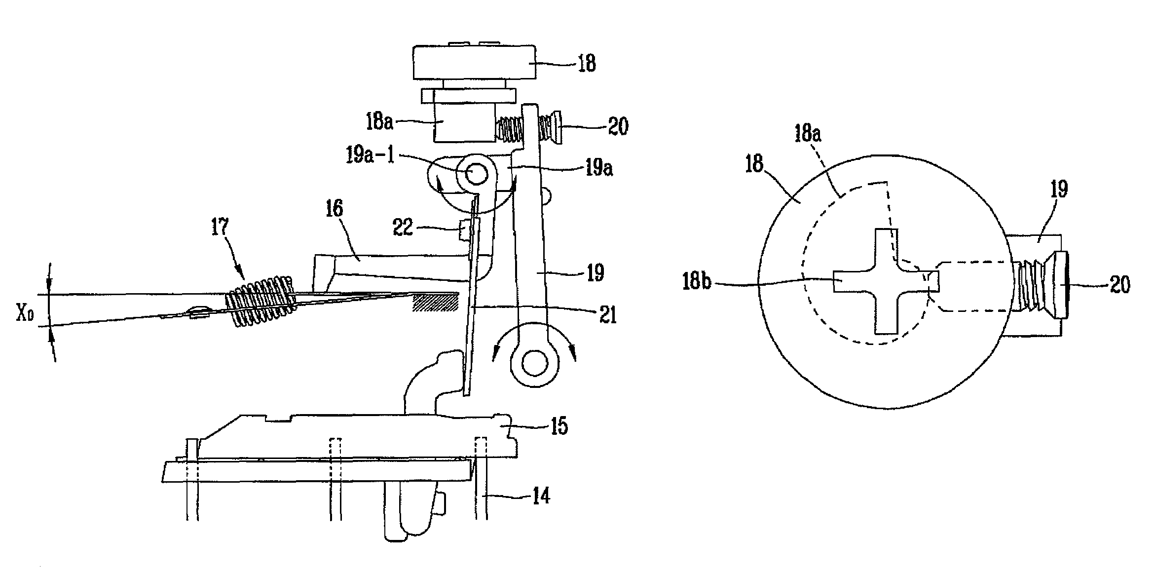
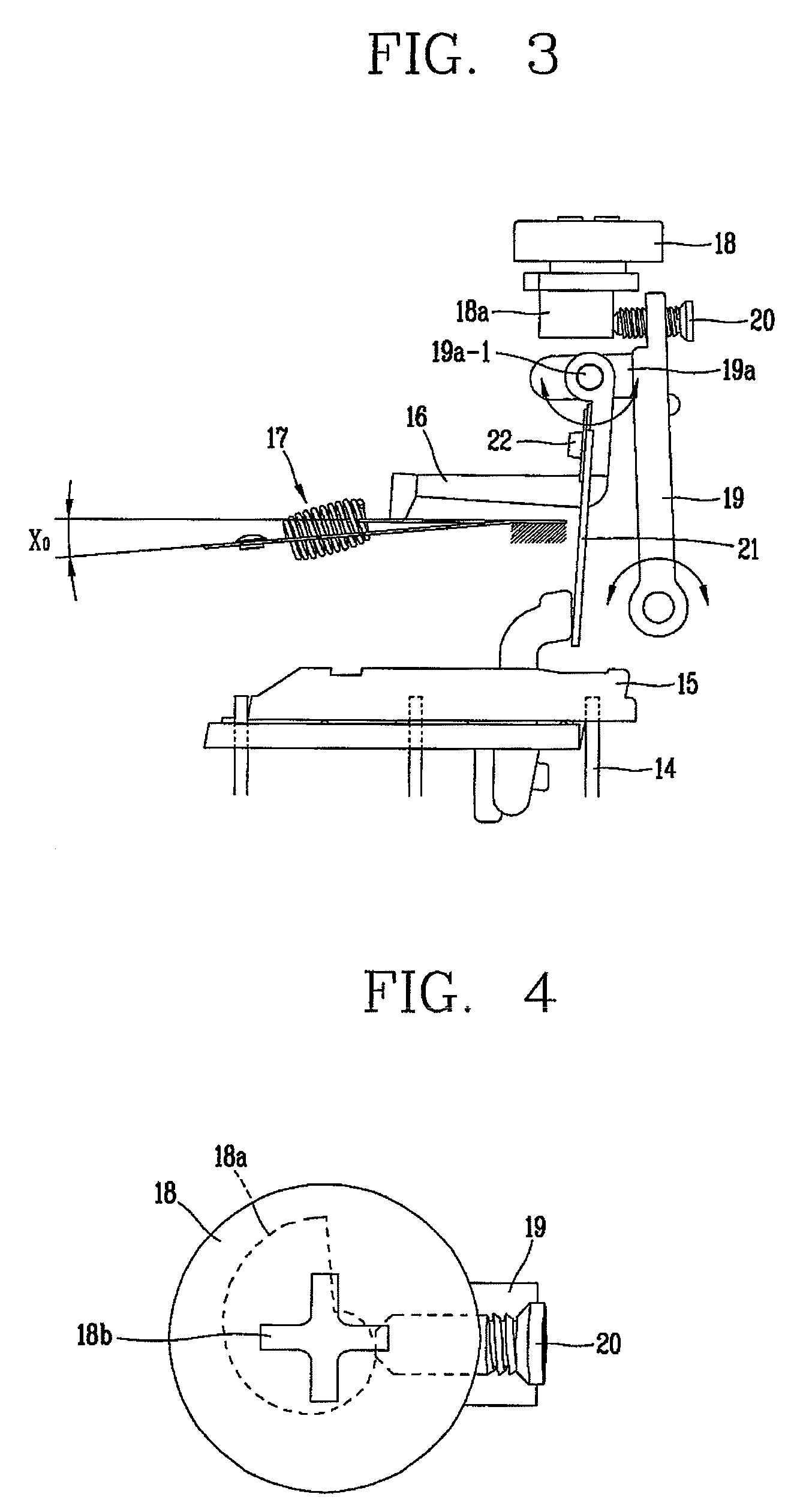
[0030]FIG. 3 is a diagram showing a configuration of a thermal overload trip apparatus in accordance with the present invention, and FIG. 4 is a planar view partially showing a relation between an adjusting cam and an adjusting screw for adjusting a trip sensitivity range in the thermal overload trip apparatus in accordance with the present invention.

[0031]As shown in FIGS. 3 and 4, the thermal overload trip apparatus in accordance with the present invention includes bimetals 14. The bimetals 14 serve to provide a driving force for trip operation by winding of a heater coil (not shown) generating heat when an overcurrent is generated and then being bent when the heater coil generates heat. Preferably, three bimetals 14 are disposed to be connected onto each circuit of three-phase Alternating Current.

[0032]In FIG. 3, a ref...


PUM


Abstract

A thermal overload trip apparatus capable of minimizing inferiority caused by variations during manufacturing of an adjusting means and simply adjusting sensitivity by duplicating the means for adjusting a sensitivity to a trip operation current, comprising: a trip mechanism driven to a trip position by a driving force from a shifter mechanism on occurrence of an overload in a circuit; a release lever mechanism for driving the trip mechanism to the trip position by pressing it when there is the driving force from the shifter mechanism or for releasing the trip mechanism when there is no driving force, on occurrence of the overload in the circuit; an adjusting lever for operating the release lever mechanism to be horizontally moved by rotation; an adjusting knob having an upper surface having a setting groove and a lower portion having a cam portion; and a means independently adjusting the sensitivity to the trip operation current regardless of manipulation of the adjusting knob.

Description

BACKGROUND OF THE INVENTION[0001]1. Field of the Invention[0002]The present invention relates to a thermal overload trip apparatus which is applicable to an electrical device for protecting a motor and an electrical load device, such as a thermal overload relay or a manual motor starter, more particularly, to a thermal overload trip apparatus which is capable of efficiently adjusting a sensitivity thereof using an adjusting screw without adjusting an adjusting knob and a method for adjusting a trip sensitivity thereof.[0003]2. Description of the Related Art[0004]An overload protecting function, a basic function of a thermal overload trip apparatus, is implemented by performing a trip operation when an overload or overcurrent within a current range satisfying a pre-set condition for the trip operation is generated in an electric circuit. The current range may refer to a current range for the trip operation according to an IEC (International Electrotechnical Commission) standard speci...

Claims


Application Information

Patent Timeline
Patent Type & Authority Patents(United States)
IPC IPC(8): H01H71/74H01H71/16
CPCH01H71/7445H01H2071/7454H01H2071/167H01H61/01H01H61/00
Inventor LEE, KYUNG-KU
Owner LS IND SYETEMS CO LTD
Why Eureka
Try Eureka