Float valve structure

a float valve and structure technology, applied in mechanical equipment, functional valve types, transportation and packaging, etc., can solve the problems of increasing the number of portions where sealing needs to be provided, the production cost increases with the increase in the number of portions, and the sealing performance of the float valve according to the related art is limited, so as to reduce production costs, enhance sealing performance, and facilitate opening of the valv

Inactive Publication Date: 2010-05-18
KYOSAN DENKI KABUSHIKI KAISHA
View PDF24 Cites 8 Cited by
  • Summary
  • Abstract
  • Description
  • Claims
  • Application Information

AI Technical Summary

Benefits of technology

[0019]With this structure, if the fuel level in the fuel tank is lowered even by only a small amount after the valve is closed, the float moves downward and the valve opening member, which moves downward together with the float, forcibly presses at least one portion of the valve downward, whereby a part of the valve is forcibly opened. As a result, the valve is fully opened with reliability. The valve support member is formed in an appropriate size such that the valve support member can be inserted into the upper opening. Accordingly, when the valve support member moves upward, the valve support member enters the upper opening. As a result, when the valve is closed, the valve fitted on the periphery of the valve support member is elastically deformed while contacting the valve seat. The force with which the valve is closed increases, and the valve closing performance improves.
[0020]In addition, with this structure, when the valve is opened, at least one portion of the valve is forcibly opened by the valve opening member. Accordingly, when the fuel level in the fuel tank is lowered even by only a small amount after the valve is opened, the float moves downward due to its own weight, and the valve opening member, which moves downward together with the float, strongly presses the at least one portion of the valve. Therefore, even if the pressure in the fuel tank is high, the valve can be opened easily. Also, sealing is provided at only one portion, and this seal portion may be made of, for example, rubber instead of resin. This enhances the sealing performance and reduces the production cost. In addition, because the valve support member is formed in the appropriate size such that the valve support member can be inserted in the upper opening, the valve is elastically deformed while contacting the valve seat when the valve is closed. Accordingly, sealing can be provided uniformly to the seal portion, and the valve closing performance improves.
[0023]In addition, with this structure, when the valve is opened, at least one portion of the valve is forcibly opened by the valve opening member. Accordingly, when the fuel level in the fuel tank is lowered even by only a small amount after the valve is opened, the float moves downward due to its own weight, and the valve opening member, which moves downward together with the float, strongly presses the at least one portion of the valve. Therefore, even if the pressure in the fuel tank is high, the valve can be opened easily. Also, sealing is provided at only one portion, and the seal portion may be made of, for example, rubber instead of resin. This enhances sealing performance and reduces the production cost. In addition, the wall body, which extends to the position near the bottom portion of the valve, is arranged on the top surface of the float at least at a position below the valve opening member. Accordingly, even if a part of the valve is bent downward due to repeatedly applied load, the bent portion is reliably supported on the top surface of the wall body. As a result, reduction in the valve closing performance can be reliably avoided.

Problems solved by technology

If the fuel that spilt out of the fuel tank is discharged to the canister, the canister becomes wet and unusable.
In addition, the production cost increases with increases in the number of portions where sealing needs to be provided.
Accordingly, the float valve according to the related art can offer only limited sealing performance.
Also, the double seal structure increases the production cost.
However, such a structure causes another problem that the ease in re-opening the valve is reduced, for example, a greater force is required to cause the second valve 4b to move away from the second valve seat 11.

Method used


Image

  • Float valve structure
  • Float valve structure
  • Float valve structure

Examples


first embodiment

[0055]the invention will be described with reference to FIGS. 1 to 20.

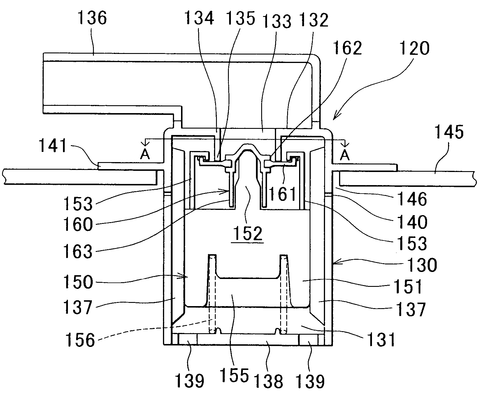
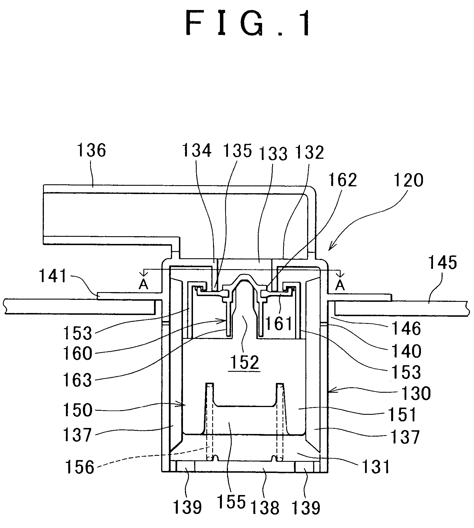
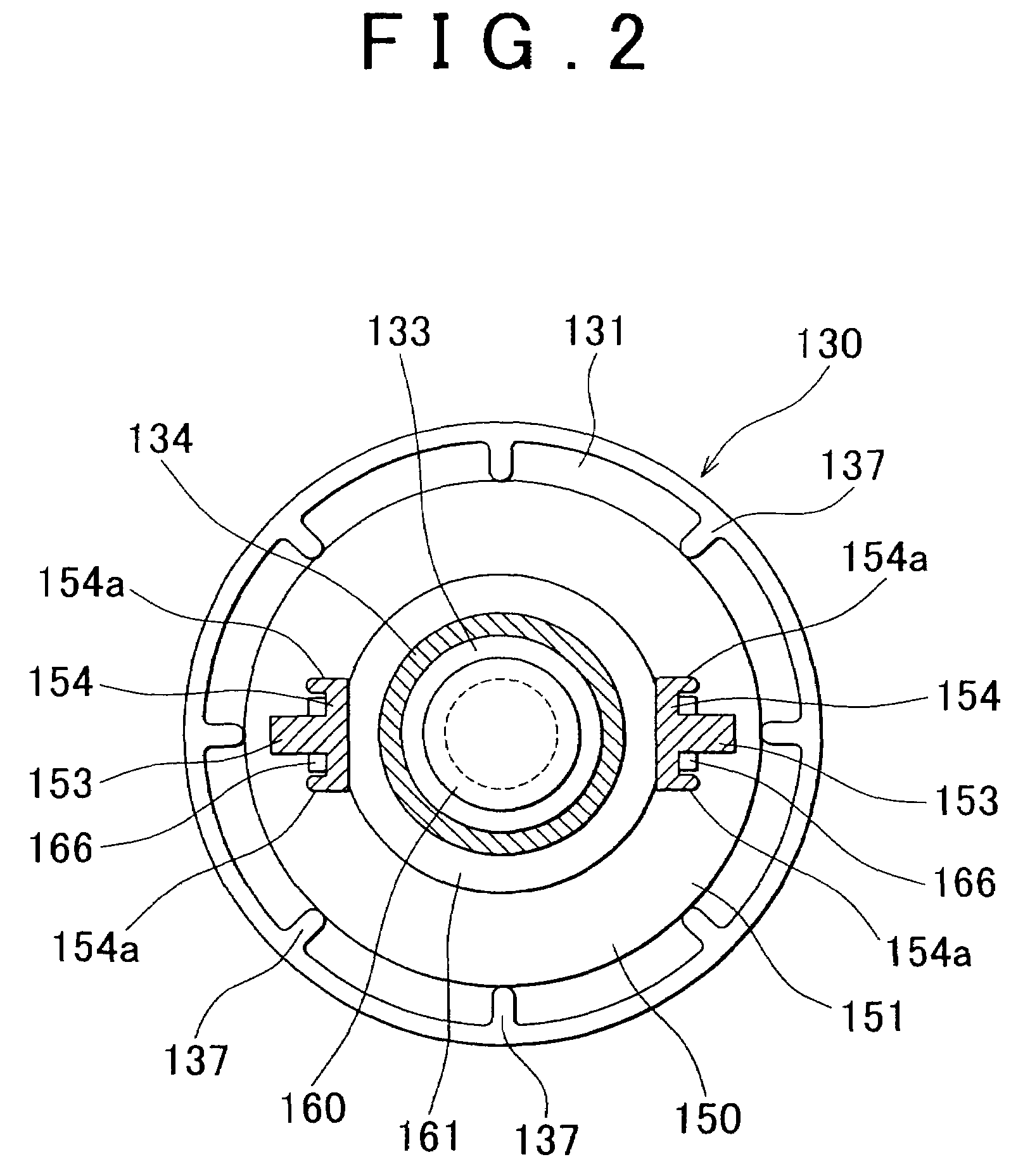
[0056]FIG. 1 illustrates the cross-sectional view of the entirety of a float valve, when a valve is closed. FIG. 2 illustrates the cross-sectional view taken along line A-A in FIG. 1. FIG. 3 illustrates the overall cross-sectional view showing the state where the float has moved downward from the position in FIG. 1, in which the valve is closed, and a part of the valve is moved slightly downward. FIG. 4 illustrates the overall cross-sectional view showing the state where the float has further moved downward from the position in FIG. 3, and the part of the valve is opened. FIG. 5A illustrates the plan view of the valve, and FIG. 5B illustrates the plan view of a valve according to a modified example. FIG. 6A illustrates the plan view and the cross-sectional view of a valve opening member. FIG. 6B illustrates the plan view and the cross-sectional view of a valve opening member according to a modified example. FIG. 6...

second embodiment

[0100]Next, the invention will be described with reference to FIGS. 21 to 28.

[0101]FIG. 21 illustrates the cross sectional view of the entirety of a float valve, when the valve is closed. FIG. 22 illustrates the enlarged cross-sectional view showing the portion near a valve support member in FIG. 21. FIG. 23 illustrates the enlarged cross-sectional view showing the state where a part of the valve is forcibly opened by a pressing portion of the valve opening member. FIG. 24 illustrates the state where the valve is fully opened. FIG. 25 illustrates the enlarged cross-sectional view of the valve opening member. The use of the float valve according to the second embodiment of the invention is not particularly limited. In the description below, however, the float valve according to the second embodiment is used for a fuel system for a motor vehicle.

[0102]The float valve 220 includes the case 230, the float 250 arranged in the case 230, the valve support member 260, the flange 241 that fi...


PUM


Abstract

A float valve structure that includes a case; a valve seat that is formed at an end portion of the case, at a position near an upper opening of the case; a float that is arranged in a space formed in the case so as to be vertically movable; a valve support member that is arranged above the float and that can be inserted into the upper opening; a valve that is fitted to the valve support member and that can contact the valve seat; and a valve opening member that can vertically move together with the float and that opens at least one portion of the valve.

Description

INCORPORATION BY REFERENCE[0001]The disclosure of Japanese Patent Applications No. 2005-199517 filed on Jul. 8, 2005 and No. 2005-317874 filed on Nov. 1, 2005 including the specification, drawings and abstract are incorporated herein by reference in their entireties.BACKGROUND OF THE INVENTION[0002]1. Field of the Invention[0003]The invention generally relates to a float valve structure. The invention relates, for example, to a float valve structure in which fuel evaporative gas in a fuel tank of, for example, a motor vehicle flows to a canister and is then absorbed in an absorbent in the canister, or the fuel in the fuel tank is prevented from flowing to the canister when a fuel level rises.[0004]2. Description of the Related Art[0005]A motor vehicle or the like includes a fuel tank that stores fuel to be supplied to a combustion chamber of an engine. The fuel tank is provided with a ventilation system to permit air to appropriately flow in / out of the fuel tank in accordance with d...

Claims


Application Information

Patent Timeline
Patent Type & Authority Patents(United States)
IPC IPC(8): B60K15/035
CPCF16K24/044Y10T137/0874Y10T137/3099
Inventor TAGAMI, HIROYAMAKITA, JUNOOSAKI, HIROSHI
Owner KYOSAN DENKI KABUSHIKI KAISHA
Why Eureka
Try Eureka