Headrest for vehicles

a headrest and vehicle technology, applied in the field of headrests, can solve the problems of high cost, complex structure of the headrest disclosed in this publication, and high cost, and achieve the effect of easy fine adjustmen

Active Publication Date: 2010-05-18
BIZEN HATSUJO
View PDF14 Cites 23 Cited by
  • Summary
  • Abstract
  • Description
  • Claims
  • Application Information

AI Technical Summary

Benefits of technology

[0007]With the above in mind, it is an object of the present invention to provide a headrest, in which, with an employment of the characteristics of a coil spring type torque limiter, the headrest can receive a rearward direction strong force and can easily be finely adjusted by being capable of turning with a light force in the forward direction, so that the position of the head-receiving member of the headrest can be finely adjusted to accord with the passenger's physique.
[0008]It is another object of the present invention to provide a headrest that is foldable so as not to interfere with the visual range of the driver when no passenger is on board, and, in addition, it includes a fewer members and parts so that the headrest is inexpensive. With respect to this point, the same is true for a so-called butterfly-type headrest in which the side parts of a headrest can be turned horizontally, in order to alleviate fatigue in the neck and the like of a passenger, supporting the sides of the head of the passenger, during long-distance movement or napping or the like, in addition to fore and aft tilting.
[0012]a winding direction of the coil spring is set in a direction that tightens the spring by a rearward turning of the base plate, thus restricting the rearward turning of the base plate;
[0023]In the headrest of the present invention as described above, the main functional parts are the stationary shaft and the coil spring; as a result, the structure is simple and manufacture can be done at low cost. Furthermore, the angular adjustment of the base plate can be done in a stepless fashion, and, when a large force is acted on the base plate, rearward turning is restricted, so that the safety is secured. In the structure of the present invention, consideration is given to the restricting force and the manipulation force during the angular adjustment when establishing the relationship between the inner diameter of the coil spring and the outer diameter of the stationary shaft; however, when the inner diameter of the coil spring is made 2 to 4% smaller than the diameter of the stationary shaft as in the present invention, the forward turning of the headrest during the angular adjustment can be done with a light force, and the rearward turning also can be made even though some greater level of force is required. Nevertheless, an adequate resisting force can be derived against the normal load pushing the head rearward. In addition, because the rearward turning restricting force can be released, when rearward turning is necessary during the angular adjustment, it can be accomplished with an extremely light force. Furthermore, the angle adjustment range and the retracting position can be switched by the control member; and when a necessary release manipulation is required, it can be done with a link to the release member. In addition, in the present invention, when the restriction is released or the spring is loosened, the rearward turning of the headrest becomes easier, and forward and rearward angular adjustments can be made with a light one-touch force by turning the base plate only, without applying a manipulation for loosening the coil spring.
[0024]Furthermore, in the headrest of the present invention that includes two coil springs, one coil spring restricts the forward turning of the base plate, while the other coil spring restricts the rearward turning thereof; as a result, both the forward and rearward turning can be restricted, and the safety of the passenger is assured against shocks resulting from a collision or emergency braking (the forces caused thereby operate both rearward and forward). Meanwhile, by turning the free ends of the respective coil springs toward the loosening side by the release member, the restrictions on both the forward turning and rearward turning of the base plate can be released. In this structure, the turning of the base plate is definitely restricted by the front end and back end of the angle adjustment range. As a result, the safety of the passenger against the shocks of a collision or emergency braking is secured, and assured holding in the retracting position can be secured.
[0025]Furthermore, in the headrest of the present invention, in addition to the adjustment for the angle of the headrest, fore and aft movement of the headrest is also adjustable. According, it is possible to comply with the passenger's physique or the like even better. Furthermore, when the passenger puts the seat back down and reclines, his or her head is prevented from falling off the headrest by the side parts of the headrest. In addition, the base plate (head-receiving member) has a function to make fore and aft tilting.

Problems solved by technology

Such a configuration is disclosed in, for example, Japanese Utility Mode Application Laid-Open (Kokai) No. 5-048750; however, the headrest disclosed in this publication is very complex in structure and high in cost.
In the headrest disclosed in Japanese Patent Application Laid-Open (Kokai) 2006-264431, the headrest can be moved or tilted using an electric motor; however, the structure of this headrest also requires many numbers of members and parts, and the headrest is expensive.
However, in this structure, a manipulation, using a manipulating member, is required to engage or disengage a latching body for latching the engagement teeth, and the latching position is limited to the position of the tooth surfaces of the engagement teeth (stepwise); as a result, stepless-fashion fine adjustments cannot be made, which is a drawback.

Method used


Image

  • Headrest for vehicles
  • Headrest for vehicles
  • Headrest for vehicles

Examples


Embodiment Construction

[0040]Embodiments of the present invention will be now described with reference to the accompanying drawings.

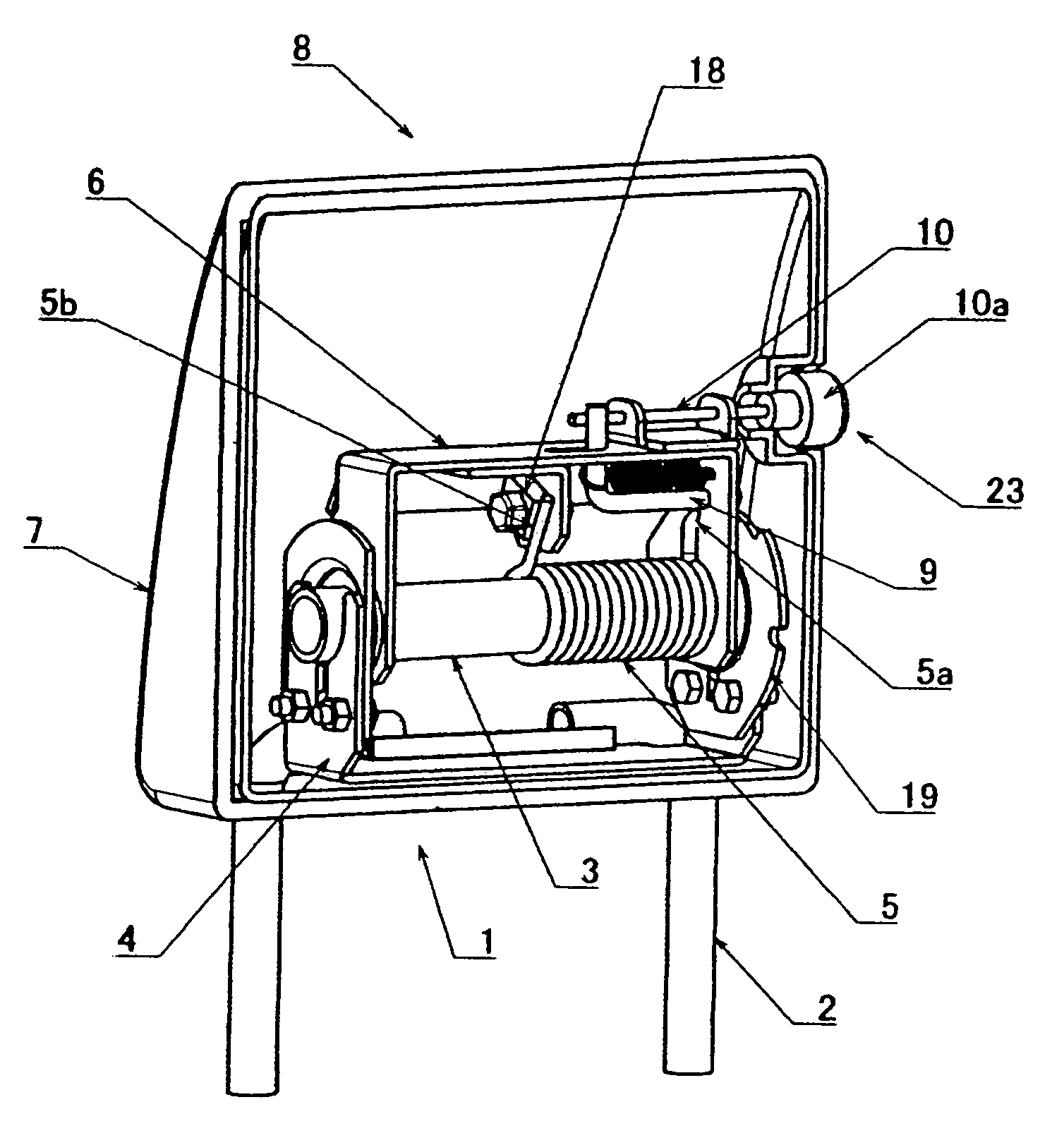
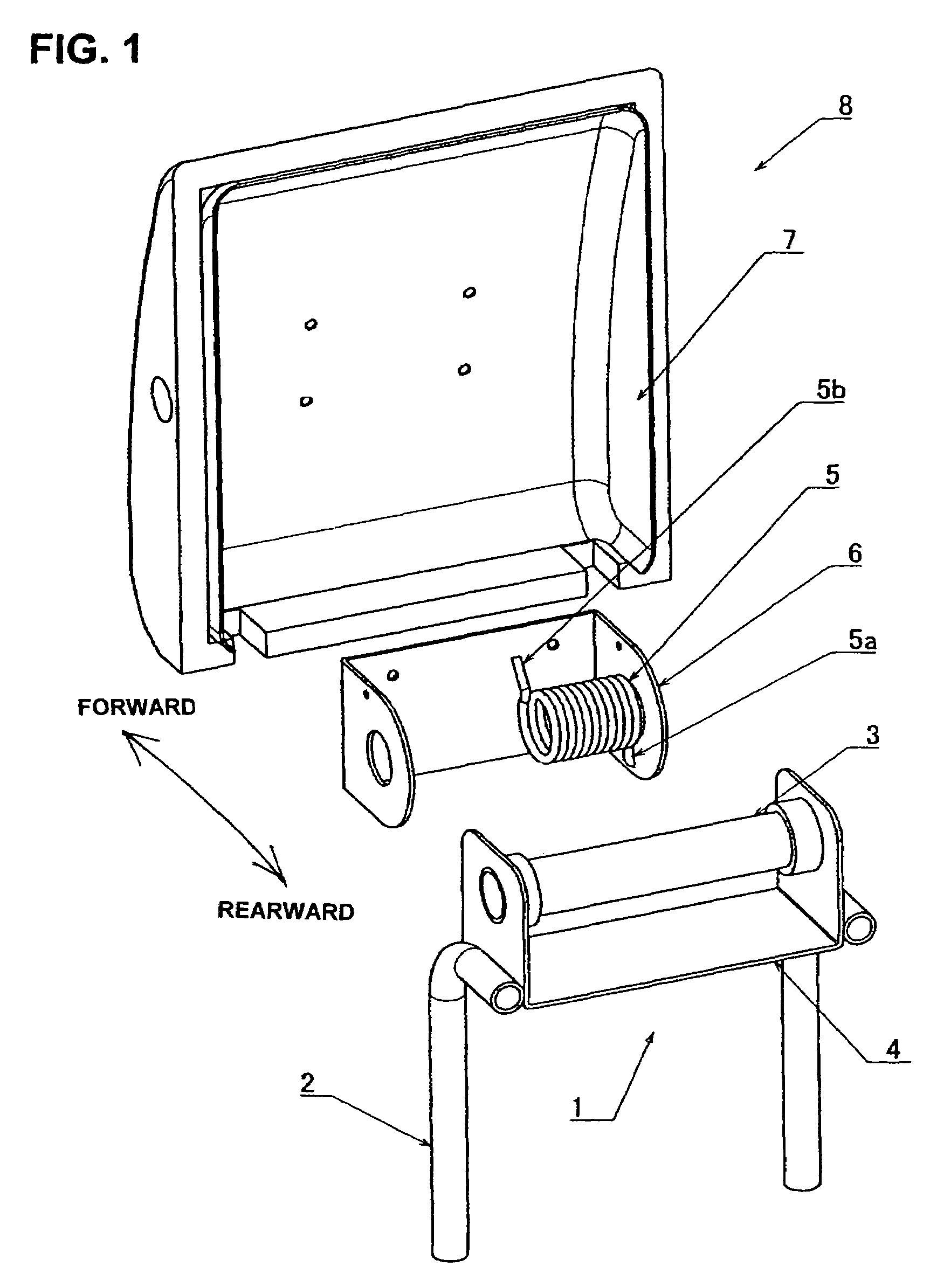
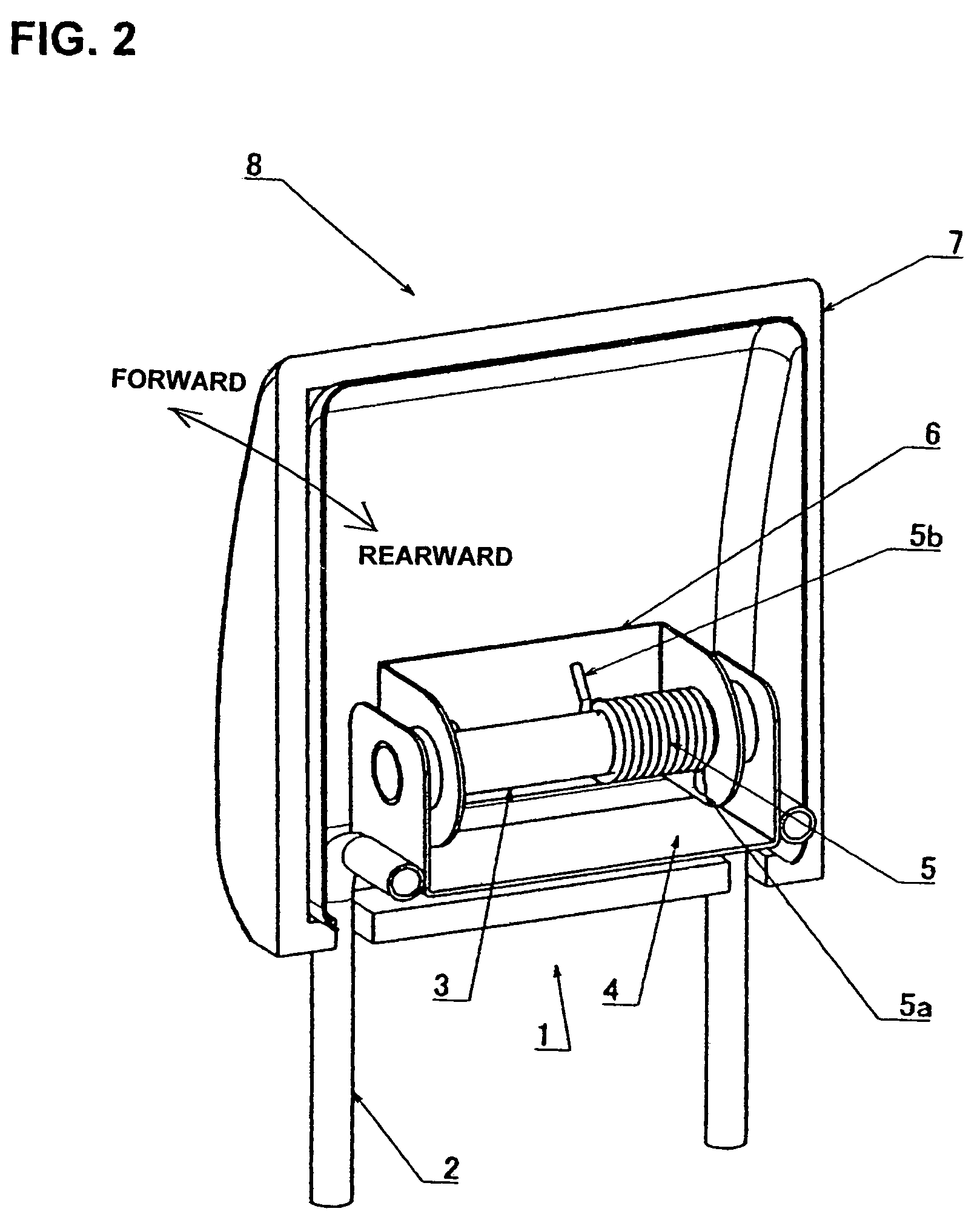
[0041]FIG. 1 is an exploded view of a headrest of the present invention, while FIG. 2 shows the assembled condition thereof. The headrest 8 of this example comprises: an attachment shaft 3 that is secured, so as to be oriented left and right (horizontally), to a stationary plate 4 which is attached integrally to a pair of left and right supporting pillars 2 that are inserted into the upper end of an automobile seat back 1; a base plate 6 that makes a core of a head-receiving member 7 which is fitted on the attachment shaft 3 so that the head-receiving member 7 can turn relative to the attachment shaft 3; and a coil spring 5 that is wound about the attachment shaft 3.

[0042]In this structure, the coil spring 5 is turnable together with the base plate 6, with one end of the coil spring 5 being a free end 5b, and the other end being a fixed end 5a that is secured to the base plat...


PUM


Abstract

A headrest for vehicles including a stationary plate secured to the seat back of a vehicle; an attachment shaft supported by the stationary plate; a coil spring wound on the attachment shaft and having a fixed end and a free end with its inner diameter being smaller than the outer diameter of the attachment shaft; and a headrest base plate attached to the stationary plate so as to turn forward and rearward. The fixed end of the coil spring is fixed to the base plate so as to secure the attachment shaft to the base plate or the fixed end of the coil is fixed to the stationary plate so as to secure the attachment shaft to the base plate, and the winding direction of the coil spring is set in a direction that tightens the spring when the base plate is turned rearward, thus restricting this rearward turning.

Description

BACKGROUND OF THE INVENTION[0001]1. Field of the Invention[0002]The present invention relates to a headrest attached to a seat back of a vehicle seat, and more particularly to a headrest mounted on a seat back for the front passenger seat or rear seat.[0003]2. Description of the Related Art[0004]A headrest will be comfortable if the angle of forward inclination thereof can be finely adjusted to match the passenger's physique or the like. It is also convenient if the sides of the passenger's head are supported together with the back of the head in cases such as when the seat is reclined. Furthermore, if the headrest can be moved forward and rearward, it will be even easier to adjust to the passenger's physique or the like. In addition, for a front passenger seat or a rear seat, when there is no passenger sitting therein, the driver's field of view being blocked can be prevented if the headrest is folded up or retracted. Such a configuration is disclosed in, for example, Japanese Util...

Claims


Application Information

Patent Timeline
Patent Type & Authority Patents(United States)
IPC IPC(8): A47C1/10
CPCB60N2/43B60N2/4858B60N2/485B60N2/4847B60N2/847B60N2/85B60N2/859
Inventor YAMANE, TAKESHIKOBAYASHI, TOKUZOOKAMOTO, AKIHIKO
Owner BIZEN HATSUJO
Why Eureka
Try Eureka