Liquid ejection apparatus and liquid maintenance method

a technology of liquid ejection and liquid maintenance, which is applied in the direction of printing, etc., can solve the problems of poor color reproduction, density non-uniformities or distortions, and deterioration of quality, and achieve the effect of stable liquid ejection and deterioration of liquid quality

Inactive Publication Date: 2010-05-18
FUJIFILM CORP
View PDF5 Cites 2 Cited by
  • Summary
  • Abstract
  • Description
  • Claims
  • Application Information

AI Technical Summary

Benefits of technology

[0015]The present invention has been contrived in view of the foregoing circumstances, an object thereof being to provide a liquid ejection apparatus and a liquid maintenance method whereby it is possible to prevent deterioration of the quality of liquid as a result of aggregation and / or settling of micro-particles in the liquid, and to eject liquid in a stable fashion.
[0017]According to the present invention, since the liquid ejection head is switched between the state where the nozzles are orientated in the downward direction and the state where the nozzles are orientated in the upward direction, by turning the liquid ejection head, and since the nozzles are sealed when the nozzles are in the upward-orientated state, then the micro-particles dispersed in the liquid do not aggregate and settle toward the free surface of the liquid in the nozzles, and therefore, blockages of the nozzles are prevented and the liquid can be ejected in a stable fashion.
[0019]According to this aspect of the present invention, since the liquid ejection head is caused to swing and the liquid inside the liquid ejection head is agitated by turning the liquid ejection head, then the micro-particles that have aggregated and settled can be redispersed more readily in the liquid than in a case where the aggregated and settled micro-particles are displaced in the vertical direction only, and therefore density non-uniformities are eliminated and it is possible to eject the liquid of uniform density.
[0020]Preferably, the liquid ejection apparatus further comprises a vibrating device which vibrates the liquid in the pressure chambers slightly to an extent which does not cause the liquid to be ejected from the nozzles, during the turning device making the liquid ejection head swing.
[0021]According to this aspect of the present invention, the micro-particles that have aggregated and settled are broken up by the slight vibration of the liquid, and greater effect of agitation is obtained by the slight vibration.
[0025]According to the present invention, deterioration of liquid quality due to aggregation or settling of micro-particles in the liquid is prevented, and stable ejection of liquid is achieved.

Problems solved by technology

When the liquid in which the micro-particles have aggregated and settled is ejected, then there is deterioration of quality in the ejection results, namely, density non-uniformities or distortions, poor color reproduction, non-uniform density of the micro-particles, and the like.
However, in some cases, it is difficult to achieve efficient agitation of liquid in which dispersed micro-particles are suspended.
In particular, in a liquid ejection apparatus having a liquid ejection head in which the liquid ejection face is situated in a bottommost position, nozzle blockages are liable to occur due to sedimented micro-particles in the nozzles.
As described above, technology has been proposed for carrying out various maintenance operations, such as the vertical swinging of the liquid ejection head, the slight vibration of the free surface of the ink in the nozzle, the discarding of the ink, and the like; however, these operations are difficult to apply in practice, since they are not efficient because of long waiting times, increased costs, and so on.
The liquid having the aggregated and settled micro-particles in the liquid cartridge is thus agitated only by the displacement of the liquid ejection head in the substantially perpendicular direction, and hence the agitation performance is low and a long time is required until the liquid is agitated to a satisfactory extent.
In Japanese Patent Application Publication No. 2004-216809, since valuable liquid is ejected and discarded when the apparatus is not in printing, there is a problem in that costs increase.
In Japanese Patent Application Publication No. 2003-72104, since the dispersed state of the micro-particles is maintained by continuously agitating the liquid by means of the piezoelectric element, then it is not effective unless the piezoelectric element continuously carries out the agitating operation even while the apparatus is not operating, and it results in high power consumption and increased costs.
Consequently, quality deterioration occurs in the ejection results.

Method used


Image

  • Liquid ejection apparatus and liquid maintenance method
  • Liquid ejection apparatus and liquid maintenance method
  • Liquid ejection apparatus and liquid maintenance method

Examples


Embodiment Construction

Liquid Ejection Head

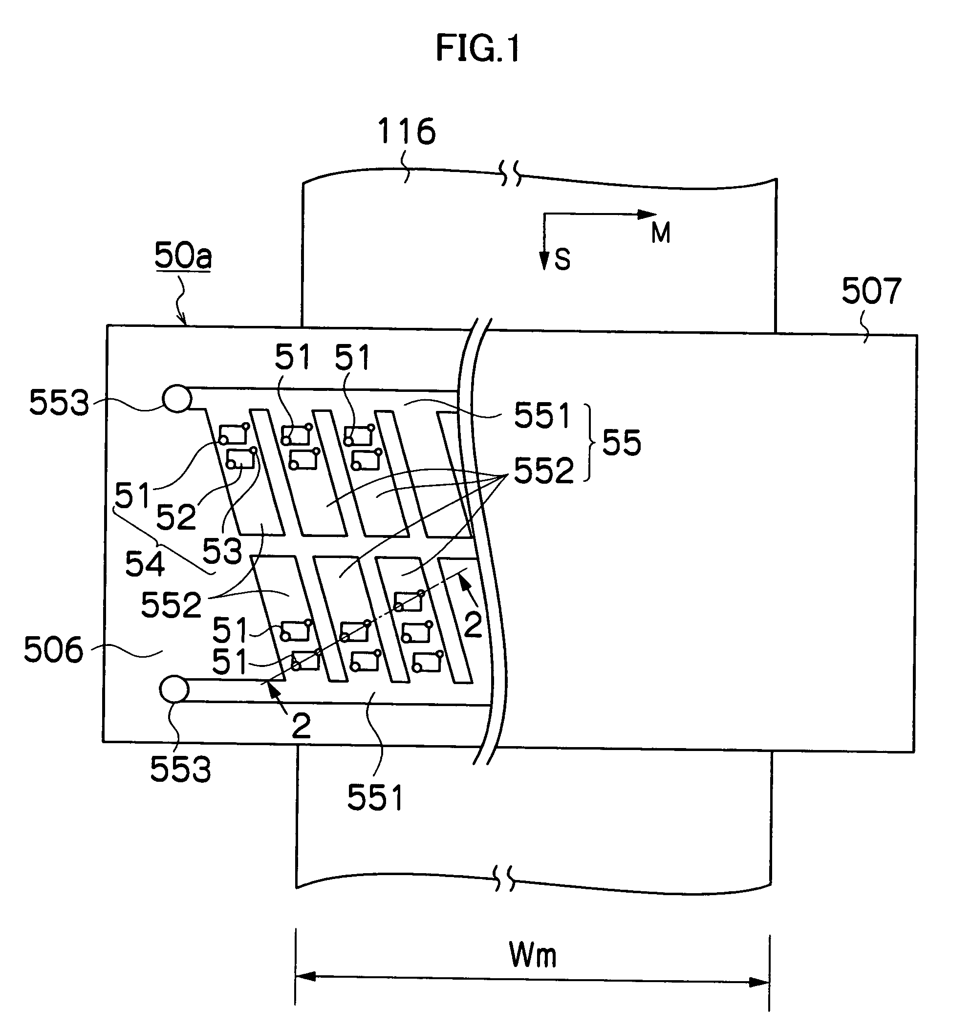
[0043]FIG. 1 is a plan diagram showing the general structure of a liquid ejection head according to an embodiment of the present invention, giving a perspective view of the left-hand half in the diagram.

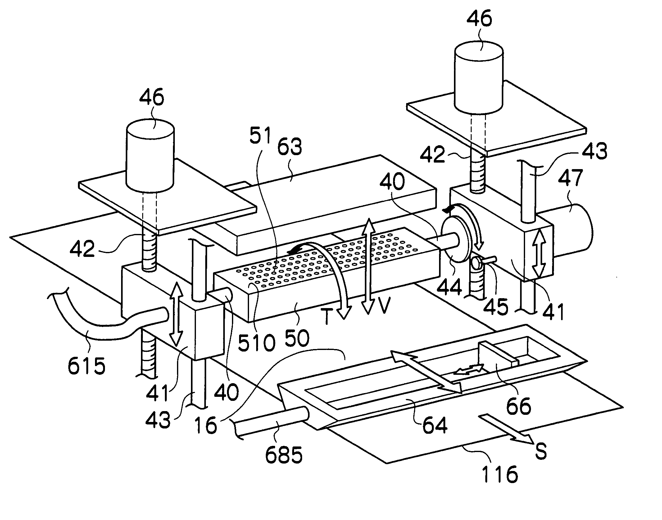
[0044]The liquid ejection head 50a shown in FIG. 1 is a so-called full line head, having a structure in which a plurality of liquid ejection ports or nozzles 51, which eject liquid toward an ejection receiving medium or a recording medium 116, are arranged through a length corresponding to a width Wm of the recording medium 116 in a main scanning direction indicated by arrow M in FIG. 1 perpendicular to a sub-scanning direction indicated by arrow S in FIG. 1, which is a conveyance direction of the recording medium 116.

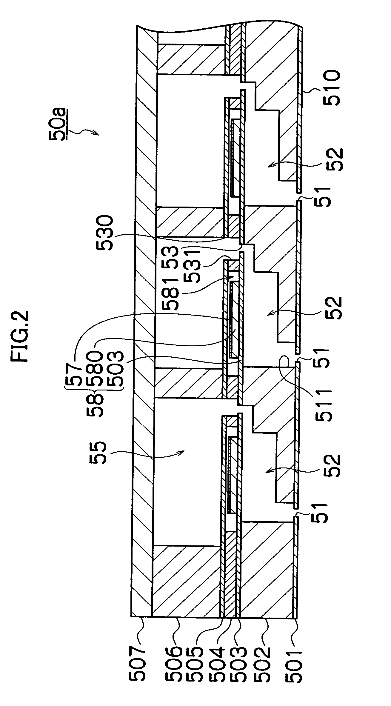
[0045]More specifically, the liquid ejection head 50a has a composition in which a plurality of pressure chamber units 54, each having the nozzle 51, a pressure chamber 52 connected to the nozzle 51, and an opening section serving as a liquid supply ...


PUM


Abstract

The liquid ejection apparatus comprises: a liquid ejection head which has nozzles ejecting liquid in a downward-facing state and pressure chambers connected to the nozzles; a turning device which turns the liquid ejection head to switch the nozzles of the liquid ejection head between the downward-facing state and an upward-facing state; and a sealing device which seals the nozzles when the nozzles of the liquid ejection head are in the upward-facing state.

Description

BACKGROUND OF THE INVENTION[0001]1. Field of the Invention[0002]The present invention relates to a liquid ejection apparatus and a liquid maintenance method, and more particularly, to a liquid ejection apparatus which ejects liquid toward a prescribed medium and a liquid maintenance method which maintains the state of the liquid.[0003]2. Description of the Related Art[0004]There is a liquid ejection apparatus which ejects dispersion liquid in which dispersed micro-particles are suspended. Examples of material of the micro-particles include, for instance, pigment, high-polymer resin, metal, glass, or oxide or compound of these. Generally, the micro-particles tend to aggregate and settle with the passage of time. When the liquid in which the micro-particles have aggregated and settled is ejected, then there is deterioration of quality in the ejection results, namely, density non-uniformities or distortions, poor color reproduction, non-uniform density of the micro-particles, and the l...

Claims


Application Information

Patent Timeline
Patent Type & Authority Patents(United States)
IPC IPC(8): B41J2/165
CPCB41J2/16511
Inventor TAKATSUKA, TSUTOMU
Owner FUJIFILM CORP
Why Eureka
Try Eureka