Shielded connector for reducing the deflection of the terminal

a shielded connector and terminal technology, applied in the direction of securing/insulating coupling contact members, fixed connections, coupling device connections, etc., can solve problems such as difficulty, and achieve the effect of improving the strength of the retaining section and improving the electrical connection

Inactive Publication Date: 2010-05-18
HON HAI PRECISION IND CO LTD
View PDF5 Cites 11 Cited by
  • Summary
  • Abstract
  • Description
  • Claims
  • Application Information

AI Technical Summary

Benefits of technology

[0009]In order to achieve the objective above, a shielded connector in accordance with a preferred embodiment of the present invention comprises a metal housing defining a receiving space upwardly and at least having a first wall, a terminal insert securely attached to the first wall. The terminal insert includes a plurality of terminals molded with an insulating material, each terminal having a retaining section, which is covered by the insulating material, an enlarged portion, which extends from one end of the retaining section and is out of the insulating material, a contact section with a base portion extending from the end of the enlarged portion toward to the receiving space. And the retaining section defines a plane extending therethrough, from which the base portion is away. As a result, the strength of the retaining section is increased. When the camera module presses the contact section of the terminals, it is not easy that the retaining sections of the terminals, which is out of the insulating material, contacted to the metal housing. Therefore, a better electrical connection is provided between the camera module and printed circuit board.

Problems solved by technology

When the camera module presses the contact section of the terminals, it is not easy that the retaining sections of the terminals, which is out of the insulating material, contacted to the metal housing.

Method used


Image

  • Shielded connector for reducing the deflection of the terminal
  • Shielded connector for reducing the deflection of the terminal
  • Shielded connector for reducing the deflection of the terminal

Examples


Embodiment Construction

[0018]In the following detailed description, for purposes of explanation, numerous specific details are set forth in order to provide a thorough understanding of the present invention.

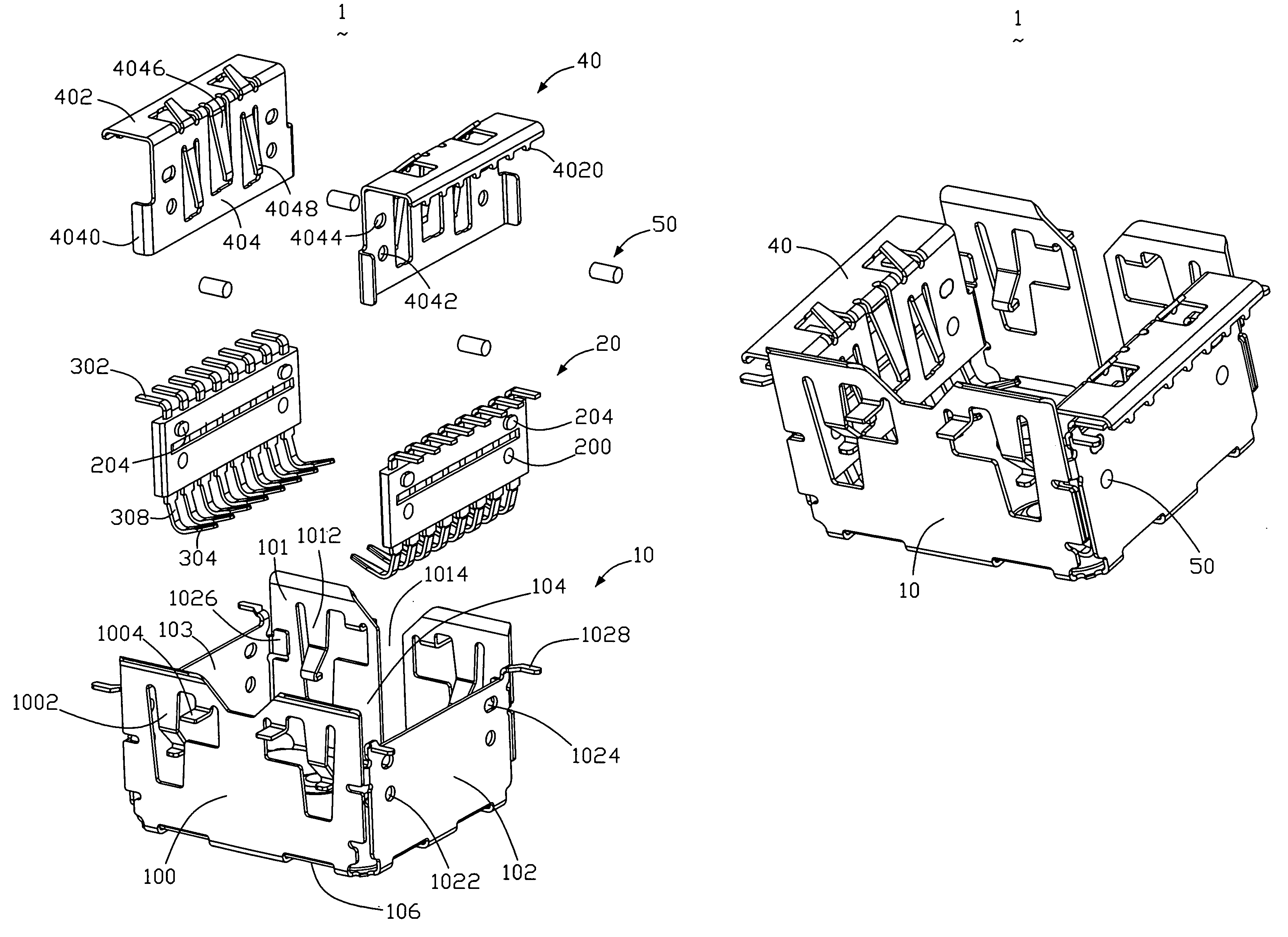
[0019]A shielded connector according to the present invention is applicable to an electronic apparatus such as digital cameras, PDAs (Personal Digital Assistants), PCs (Personal Computers), mobile phones or the like. In the preferred embodiment illustrated in FIGS. 1-6, the shielded connector 1 is used in a mobile handset (not shown) for connecting a camera module 3 to a PCB 2.

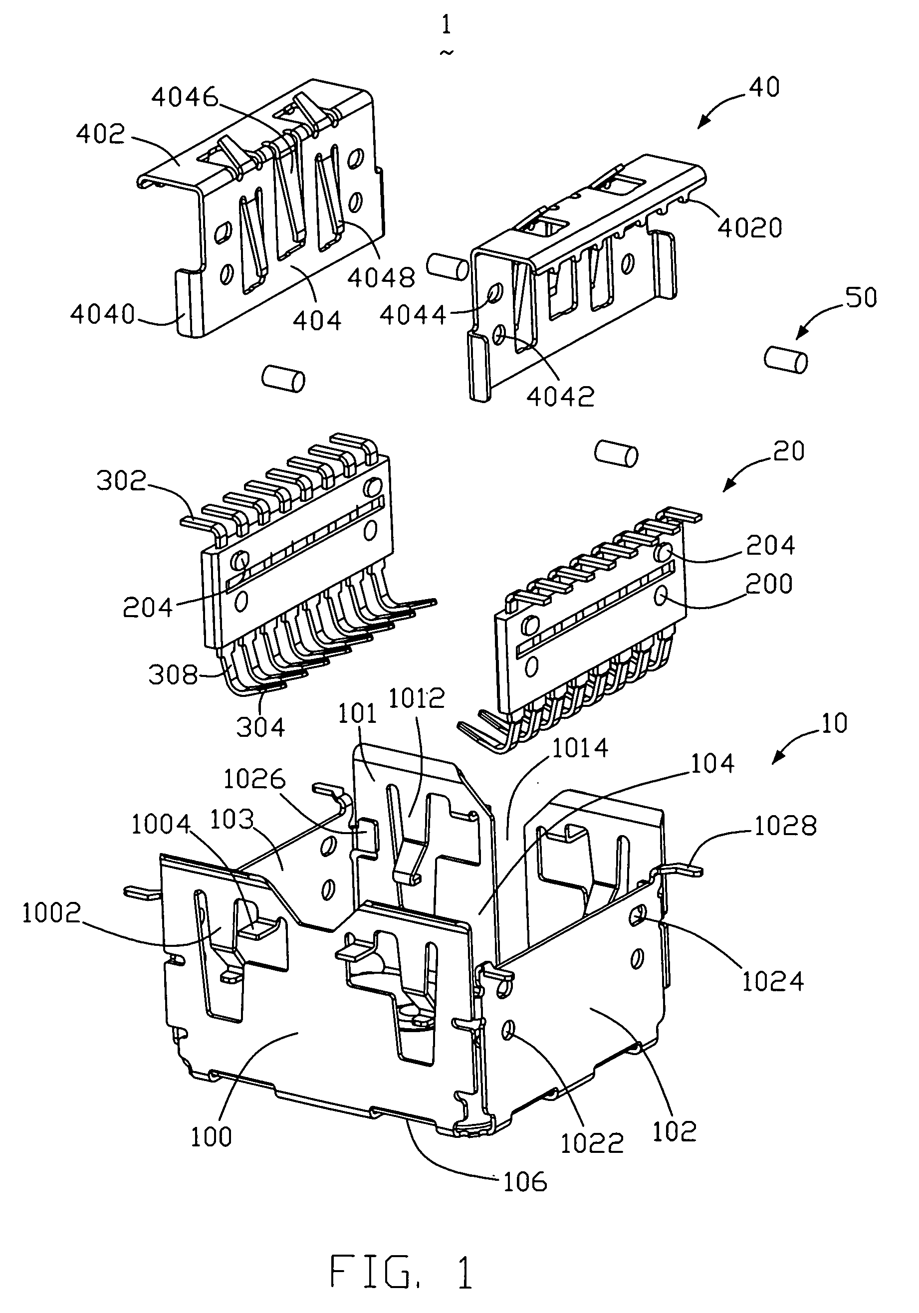
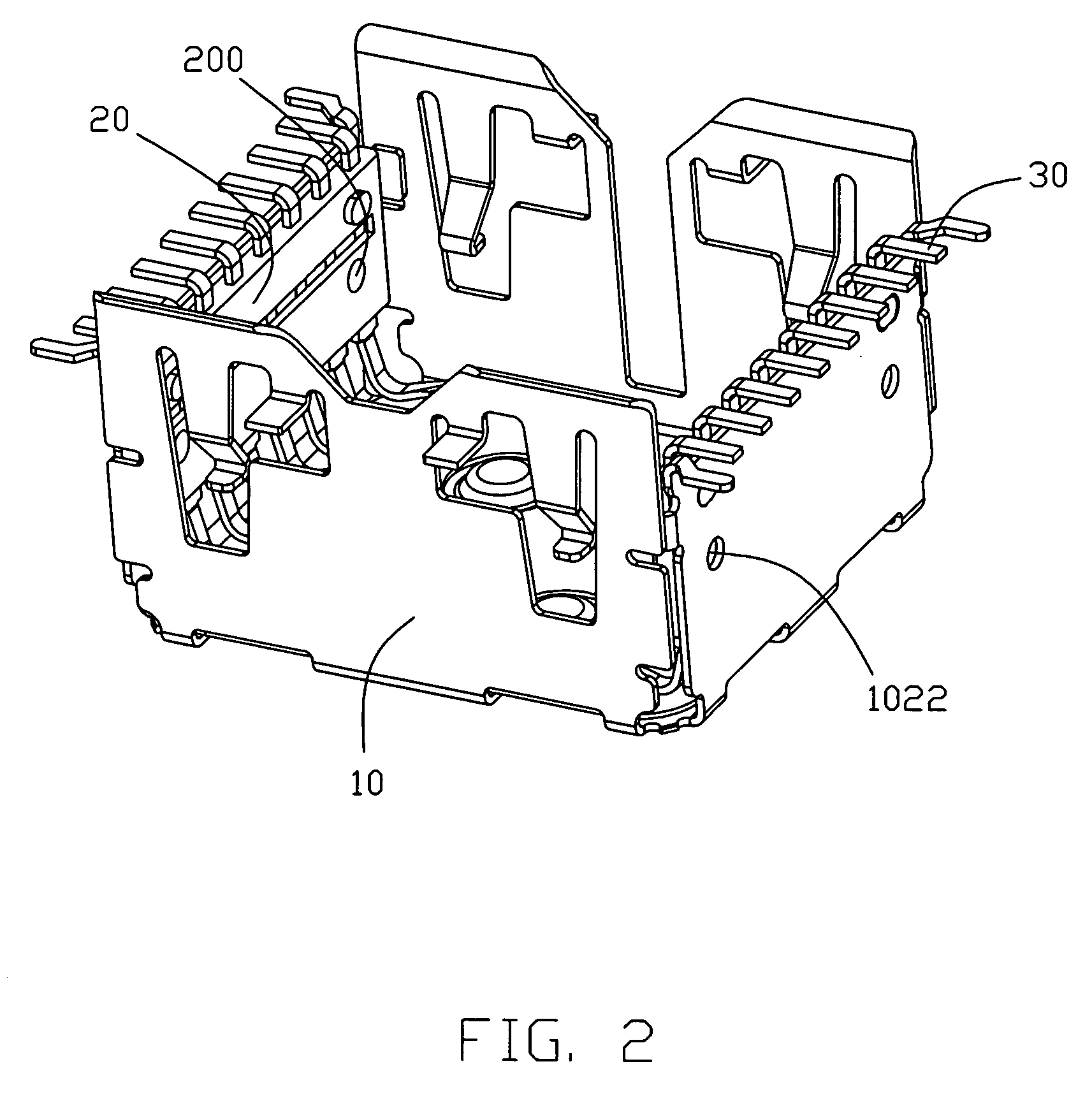
[0020]FIG. 1 is an exploded perspective view of the shielded connector 1 for receiving a camera module 3 in the embodiment of this invention. In the figure, the reference numeral 10 denotes a metal housing made of a metal material. The reference numeral 20 denotes a pair of insulating housings made of insulating material and the reference numeral 40 denotes a pair of metal shield made of metal material.

[0021]The metal housing 10 ...


PUM


Abstract

A shielded connector (1) comprises at least a metal housing (10) configured by first, second, third and fourth sidewalls (100, 101, 102, 103) defining a receiving space (104) therebetween, and first and second terminal insert securely attached to the first and third wall of the metal housing. Each terminal insert includes a plurality of terminals (30) molded with an insulating material, each terminal including at least a retaining section (300) which is covered by the insulating material, and defining a plane extending therethrough, and a contact section (304) with a base portion (308) extending from the retaining section, wherein the base portion is away from the plane defined by the retaining section. And each terminal further includes enlarged portion (306), which connected the retaining section and the contact section, and being out of the insulating material so as to effectively reduce the deflection during mating with an inserted element.

Description

BACKGROUND OF THE INVENTION[0001]1. Field of the Invention[0002]The present invention relates to a shielded connector, and more particularly to an electronic module connector for interconnecting an electronic module such as a camera module for use with a cellular phone or the like to an electrical member such as a printed circuit board. The connector includes a terminal featured with an enlarged retaining portion thereby effectively reducing deflection during mating with an inserted element.[0003]2. Description of the Related Art[0004]Conventionally, electronic modules such as a camera module for use with a cellular phone are securely maintained in electrical connection with an electronic member such as a printed circuit board. Therefore, an electrical connector for the camera module, formed in a shape that allows for secure insertion of the camera module, is pre-installed on the printed circuit board. Then, the camera module is inserted into the electrical connector to electrically...

Claims


Application Information

Patent Timeline
Patent Type & Authority Patents(United States)
IPC IPC(8): H01R13/648H01R12/55
CPCH01R13/6582H01R12/7076
Inventor MA, WEN-QIANG
Owner HON HAI PRECISION IND CO LTD
Why Eureka
Try Eureka