Variable passenger restraint controlled system

a control system and passenger technology, applied in anti-collision systems, electric devices, special data processing applications, etc., can solve the problems of device comfort and lack of driver comfort, and achieve the effect of increasing restraining performance, improving passenger protection, and high restraining performan

Inactive Publication Date: 2010-05-18
NISSAN MOTOR CO LTD
View PDF43 Cites 10 Cited by
  • Summary
  • Abstract
  • Description
  • Claims
  • Application Information

AI Technical Summary

Benefits of technology

[0005]Meanwhile, if one attempts to increase the restraining performance by merely speeding up the timing at which an emergency situation is determined to exist, the degree of passenger protection may improve but the device will be lacking from the perspective of driver comfort because it will become an annoyance.
[0006]The present invention was conceived to address these issues and its object is to provide a passenger protection device that takes the driving conditions into consideration and ensures a high restraining performance without debasing the comfort of the passenger.

Problems solved by technology

Meanwhile, if one attempts to increase the restraining performance by merely speeding up the timing at which an emergency situation is determined to exist, the degree of passenger protection may improve but the device will be lacking from the perspective of driver comfort because it will become an annoyance.

Method used


Image

  • Variable passenger restraint controlled system
  • Variable passenger restraint controlled system
  • Variable passenger restraint controlled system

Examples


first embodiment

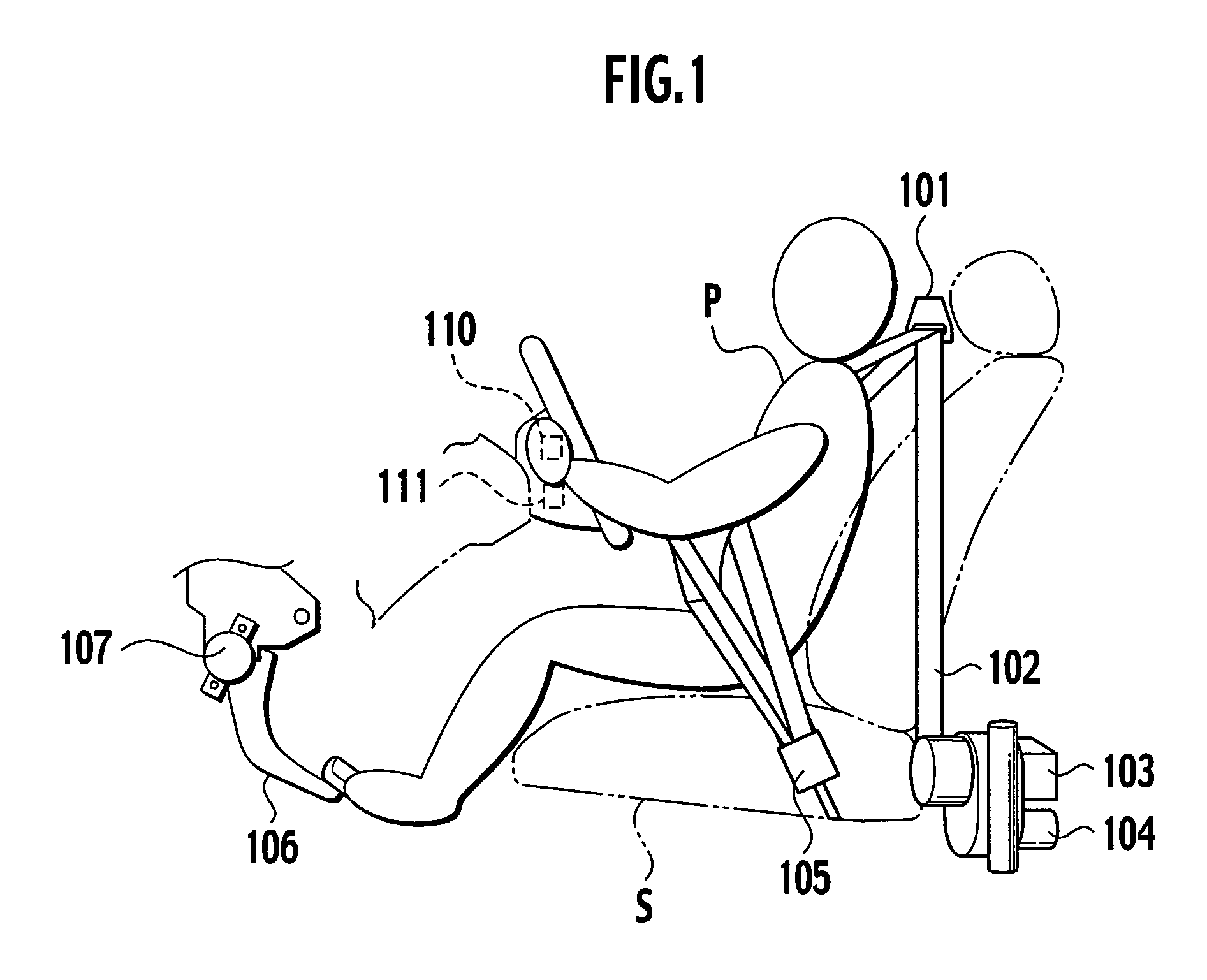
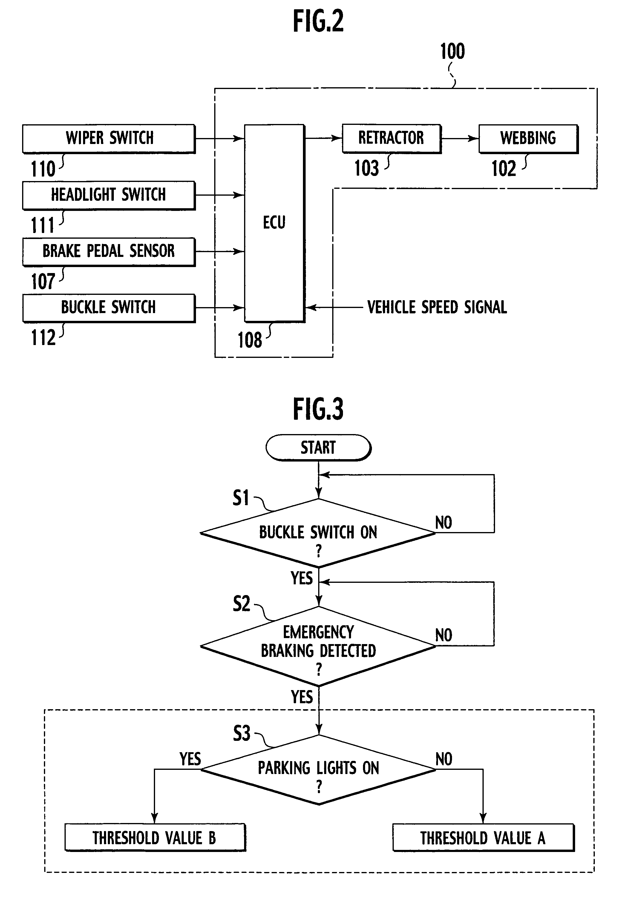
[0022]FIG. 1 is a diagrammatic view for explaining a first embodiment of a passenger protection device in accordance with the present invention. The passenger protection device 100 is provided with a webbing 102 that serves to restrain a passenger P sitting in a seat S, and a retractor 103 configured to store the webbing 102 using an electric motor 104 configured to provided power to wind up one end of the webbing 102. The other end of the seatbelt is fastened to the vehicle body through an anchor arranged on the door side of the seat S.

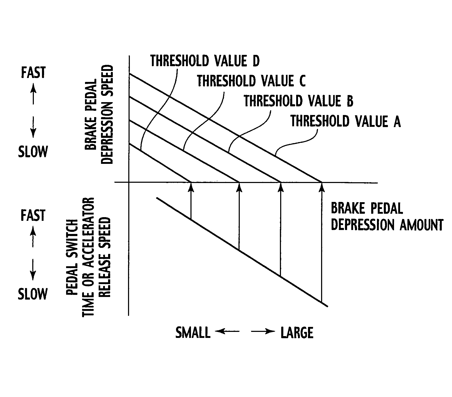
[0023]The or 103 is configured to retract the webbing 102 and inhibits of extraction of the webbing 102 when the brake pedal operation amount detected by the pedal sensor 107 exceeds a threshold value prevents the webbing 102 from being extracted (drawn out) when the vehicle experiences a prescribed deceleration.

[0024]A tongue is attached in a freely movable manner to an intermediate part of the webbing 102 and is configured to engage in a detachable...

second embodiment

[0047]FIG. 8 is diagrammatic view for explaining a second embodiment of a passenger protection device in accordance with the present invention. Descriptions of parts that are the same as those of the first embodiment are omitted. A brake pedal 106, a brake pedal sensor 107 configured to detect the movement of the brake pedal 106, an accelerator pedal 113, and an accelerator pedal sensor 109 configured to detect the movement of the accelerator pedal 109 are provided at the feet of the passenger P. The information detected by the brake pedal sensor 107 includes the timing at which the driver starts depressing the brake pedal, the amount by which the brake pedal is depressed, the speed at which the brake pedal is depressed, and other such information related to the movement of the brake pedal 106. Meanwhile, the information detected by the accelerator pedal sensor 109 includes the amount by which the accelerator pedal is depressed, the timing at which the driver starts releasing the ac...


PUM


Abstract

An aspect of the present invention provides a passenger protection device that includes, a brake pedal sensor configured to detect the amount by which a brake pedal of a vehicle is operated, a webbing, one end of the webbing fixed to the vehicle, configured to restrain a passenger seated on a seat of the vehicle, a retractor connected to the other end of the webbing, the rector configured to retract the webbing and inhibit of the webbing extraction, and an ECU electrically coupled to the brake pedal sensor, the ECU configured to detect that the brake pedal operation amount detected by the pedal sensor exceeds a first threshold value, the ECU configured to revise the threshold value based on safety related information of the vehicle to control the inhibition of the webbing extraction of the retractor.

Description

BACKGROUND OF THE INVENTION[0001]The present invention relates to a passenger protection device configured to retract the webbing of a seatbelt using an electric motor. More particularly the present invention relates to a technology for controlling the retraction of the webbing in accordance with the Situation.[0002]Japanese Laid-Open Patent Publication No. 2001-253317 discloses a passenger restraining device to determine if an emergency situation exists in which there is the possibility that the vehicle in which the passenger restraining device is installed will come abnormally close to a preceding vehicle or an obstacle and, if such an emergency situation exists, to retract the seatbelt using an electric motor. The passenger restraining device uses information regarding the operation of the brakes by the driver while driving (e.g., depression of the brake pedal, brake fluid pressure) in order to determine if such an emergency situation exists.[0003]Additionally, Japanese Laid-Open...

Claims


Application Information

Patent Timeline
Patent Type & Authority Patents(United States)
IPC IPC(8): B60R22/00E05F15/00G05D3/00B60R21/01B60R21/013B60R21/015B60R21/16B60R21/33
CPCB60R21/013B60R21/33B60R21/01546B60R2021/01311B60R2021/01272
Inventor FUKUDA, SHUNICHITOMIMATSU, KAZUNORI
Owner NISSAN MOTOR CO LTD
Why Eureka
Try Eureka