
Irritation member

Active Publication Date: 2010-05-25
RHEINMETALL WAFFE MUNITION GMBH
View PDF5 Cites 16 Cited by
  • Summary
  • Abstract
  • Description
  • Claims
  • Application Information

AI Technical Summary

Benefits of technology

[0004]It is an object of the invention to prevent displacement after the ignition of individual effect charges, so that the irritation grenade remains in essentially the same place after striking the floor, thus not injuring bystanders by means of its displacement.
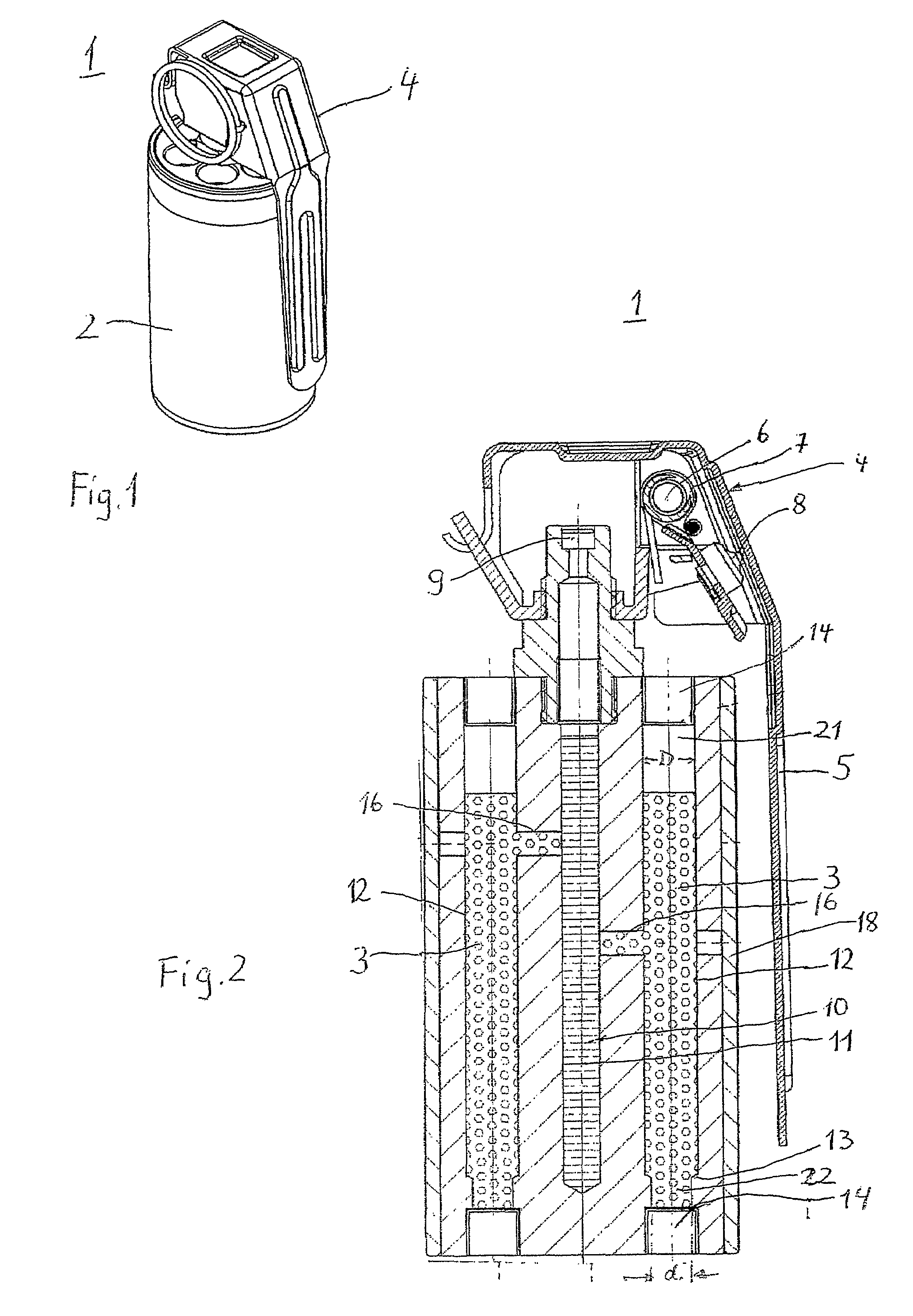
[0007]The compartments of the irritation grenade are preferably stepped drilled holes to accept the effective charges, whereby the step on the floor of the irritation grenade is provided, thus reducing the cross section of the hole there.

Problems solved by technology

It has been nevertheless shown, that after ignition of an effective charge, the irritation grenade may be displaced by several meters.
Such an uncontrolled displacement presents the hazard of injury for any persons in the vicinity, particularly with those irritation grenades with several time-offset effects, but not only with them.

Method used


Image

  • Irritation member
  • Irritation member

Examples


Embodiment Construction

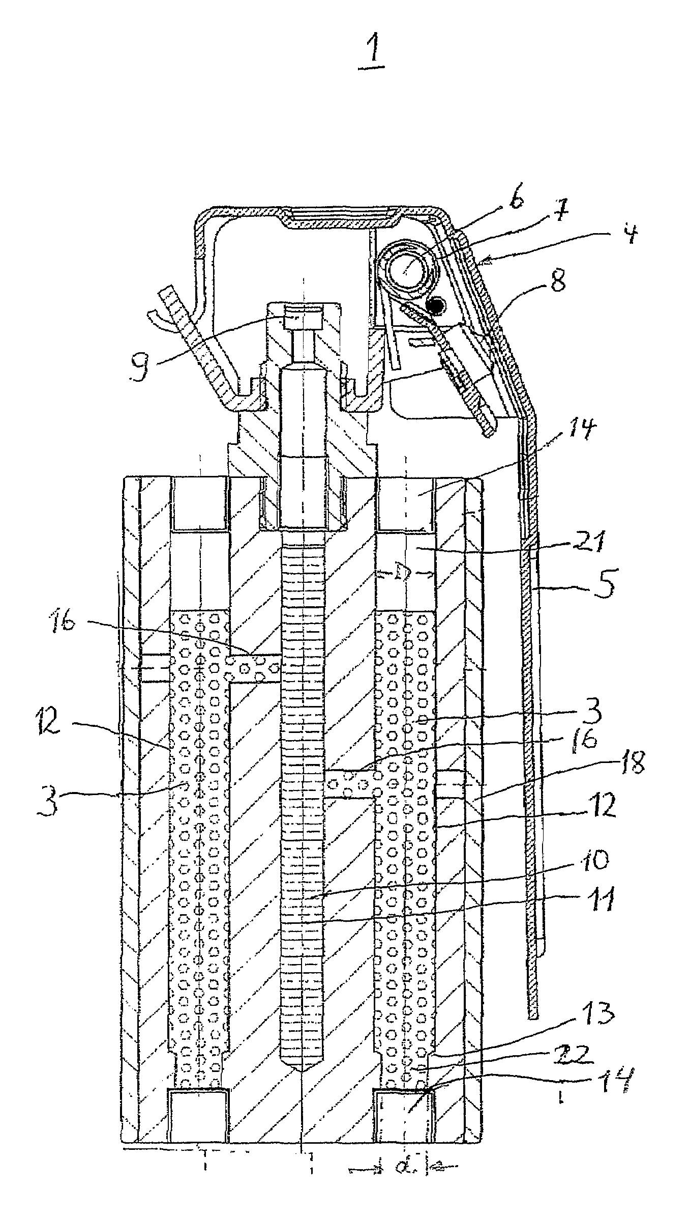
[0012]The preferred embodiments of the present invention will now be described with reference to FIGS. 1 and 2 of the drawings. Identical elements in the figures are designated with the same reference numerals.

[0013]An irritation grenade 1 includes a cylindrical receptacle 2 to accept several effective loads 3 and a rocker-arm igniter 4 mounted on the upper face of the receptacle 2 as shown in FIG. 1.

[0014]The rocker-arm igniter 4 is provided with a handgrip 5 extending almost the entire length of the receptacle 2 that may be very rapidly pivoted upward about a horizontal axis 6 above the top face of the receptacle 2 with the help of a strong pre-tensioned spring 7 as shown in FIG. 2. The handgrip 5 is usually secured using a securing pin (not shown), and is thus held in the initial position shown in FIG. 2. If the irritation grenade is used, the securing pin is removed, whereby the handgrip is held in its initial position by the user.

[0015]The rocker-arm igniter includes a striking...


PUM


Abstract

Disclosed is an irritation grenade (1) comprising a receptacle (2) with at least one compartment (12) within which an effective charge (3) is accommodated and which ends in one respective discharge port (21, 22) on opposite sides of the receptacle (2) while being locked by means of a closure (15). A rocker-arm type igniter (4) is provided to ignite the effective charges. The combustion gases of the effective charges (3) are deflected in part by parts of the rocker-arm igniter (4) such that the irritation grenade is displaced when the effective charges (3) are ignited. In order to prevent this from happening, the cross section of the discharge ports (21, 22) of the compartments (12) is embodied smaller on the side opposite the rocker-arm igniter (4) than the cross section of the discharge ports (21) on the side of the rocker-arm igniter (4) such that recoil forces which are generated when the effective charges (3) are burned and act upon the irritation grenade (1) are substantially identical on both opposite sides.

Description

BACKGROUND OF THE INVENTION[0001]The invention relates to an irritation grenade to create irritation or shock to a human being.[0002]Among other things, irritation grenades are used in hostage situations or aircraft hijackings in order to overpower the perpetrators. The irritation grenade is mainly in the form of a hand grenade with a preferably cylindrical receptacle that possesses at least one, and preferably several, chambers, e.g., drilled holes, extending parallel to the longitudinal axis and occupying the entire length of the receptacle. Said chambers contain active or effective charges such as sound or flash loads. A manually-operable igniter, usually a rocker-arm igniter, ignites a pyrotechnic delay charge that ignites the individual effect charges via ignition channels. These charges create a shock effect such as, for example, a very loud noise, a blinding flash, or similar, achieving an irritation or shock effect to the perpetrator and allowing him to be captured.[0003]An ...

Claims


Application Information

Patent Timeline
IPC IPC(8): F42B8/00
CPCF42B12/36F42B27/00F42B12/46
Inventor LUBBERS, THORSTENHAESELICH, DETLEF
Owner RHEINMETALL WAFFE MUNITION GMBH
Learn More