Supercharge Your Innovation With Domain-Expert AI Agents!

Stacker crane

a technology of stacker cranes and support posts, which is applied in the direction of lifting devices, roads, constructions, etc., can solve the problems of increasing the fore-and-aft length of the travel vehicle, the inability to narrow the gap between the pair of front and rear support posts more than a set spacing, and the inability to shorten the fore-and-aft so as to achieve the effect of shortening the length of the stacker cran

Active Publication Date: 2010-05-25
DAIFUKU CO LTD
View PDF25 Cites 7 Cited by
  • Summary
  • Abstract
  • Description
  • Claims
  • Application Information

AI Technical Summary

Benefits of technology

The present invention provides a stacker crane that can be easily shortened in length. The crane has a vehicle frame that supports the wheels and a connection frame that connects the support frames. The crane also includes support posts that guide a vertically movable platform. By arranging the support posts on the support frames, the length of the crane in the fore-and-aft direction can be shortened.

Problems solved by technology

When the stacker crane is long in the fore-and-aft direction, the range over which it moves becomes wide, and thus although it is preferable for the stacker crane to have a short fore-and-aft length, it was not possible to narrow the gap between the pair of front and rear support posts more than a set spacing that corresponds to the width of the spacing between storage racks to which articles are transferred.
This causes the front end portion and the rear end portion of the travel vehicle to project significantly outward from the positions where the support posts are supported and thus increases the fore-and-aft length of the travel vehicle and makes it difficult to shorten the fore-and-aft length of the stacker crane.

Method used


Image

  • Stacker crane
  • Stacker crane
  • Stacker crane

Examples


Embodiment Construction

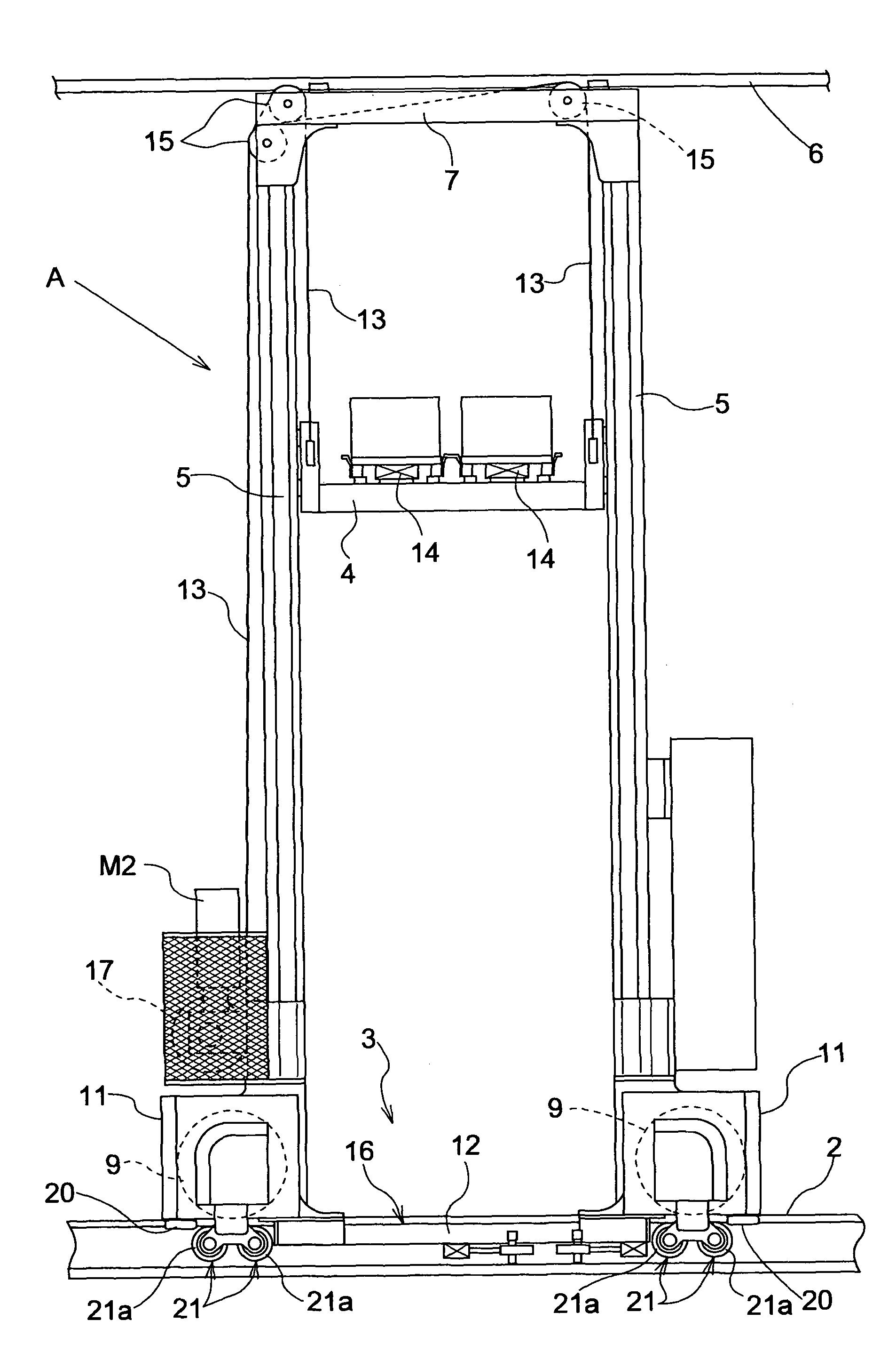
[0016]Hereinafter, embodiments of a stacker crane according to the present invention are described with reference to the drawings. Throughout the specification the term “fore-and-aft direction” is used to indicate the orientation along which the stacker crane A moves.

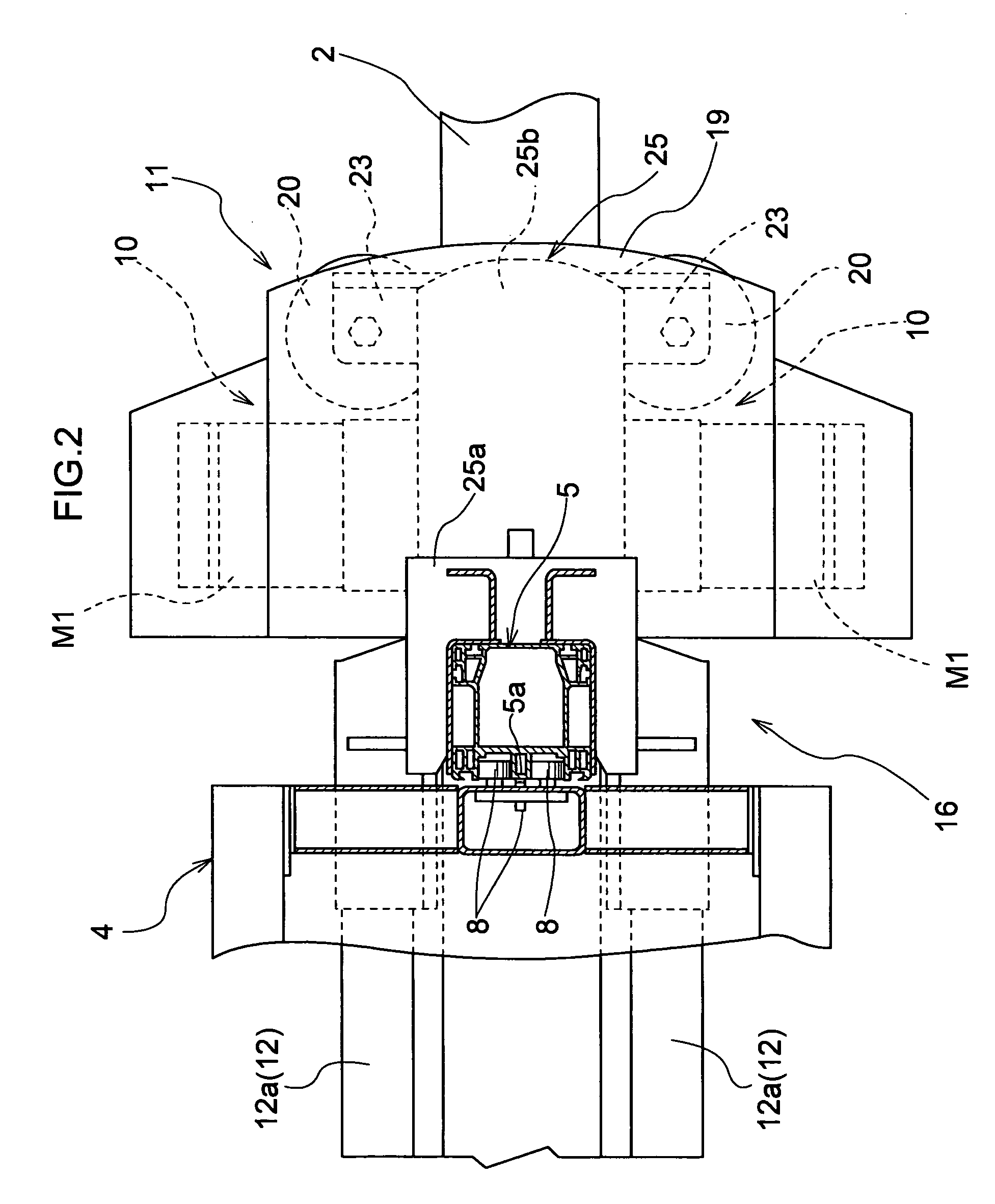
[0017]As shown in FIG. 1, a stacker crane A travels over a single travel rail 2 disposed on a floor surface along a work path formed between storage racks. A travel vehicle 3 that travels along the travel rail 2 is provided with a pair of support posts 5, with a spacing between them in the longitudinal or the fore-and-aft direction, that serve as guides for raising and lowering a vertically movable platform 4. The upper end portions of the support posts 5 are linked to each other by an upper frame 7 that is guided along a guide rail 6 disposed above the work path. The stacker crane A automatically moves over the work path and transfers articles to and from the storage racks. The stacker crane A and the storage racks tog...


PUM


Abstract

The invention provides a stacker crane, configured to move on a single rail provided along one or more racks, includes: a first wheel that moves on the rail; a second wheel that moves on the rail, and that is disposed spaced apart from the first wheel in a fore-and-aft direction; a vehicle frame supported by the first wheel and the second wheel; first drive supported by the vehicle frame for driving the first wheel. The vehicle frame includes: a first support frame for supporting the first wheel and the first drive means; a second support frame for supporting the second wheel; and a connection frame that connects the first support frame and the second support frame. The stacker crane also includes a first support post that extends vertically and whose lower end portion is connected to the first support frame; a second support post that extends vertically and whose lower end portion is connected to the second support frame; and a vertically movable platform that is guided by the first support post and the second support post, and that can move vertically with respect to the vehicle frame.

Description

BACKGROUND OF THE INVENTION[0001]The present invention relates to stacker cranes.[0002]Stacker cranes transport articles by moving a travel vehicle along a travel rail and raising and lowering a vertically movable platform on which an article is placed. In conventional configurations, the travel vehicle is constructed by connecting the lower end portions of a pair of front and rear support posts via a connection frame, and connecting a support frame that supports wheels and drive means to each of the front face of the front-side support post and the rear face of the rear-side support post, so that the lower end portions of the support posts are connected by and supported on the connecting frame and the support frames (see JP 2003-212308A, for example).[0003]When the stacker crane is long in the fore-and-aft direction, the range over which it moves becomes wide, and thus although it is preferable for the stacker crane to have a short fore-and-aft length, it was not possible to narrow...

Claims


Application Information

Patent Timeline
Patent Type & Authority Patents(United States)
IPC IPC(8): E01B25/22
CPCB66F9/072
Inventor UEDA, YUICHI
Owner DAIFUKU CO LTD
Features
  • R&D
  • Intellectual Property
  • Life Sciences
  • Materials
  • Tech Scout
  • Unparalleled Data Quality
  • Higher Quality Content
  • 60% Fewer Hallucinations
Learn More