Bicycle wheel quick release assembly

a technology for bicycle wheels and assembly parts, applied in the field of bicycles, can solve problems such as requiring separate operation of redundant retention systems, and affecting the safety of bicycles

Active Publication Date: 2010-05-25
TREK BICYCLE CORPORATION
View PDF50 Cites 20 Cited by
  • Summary
  • Abstract
  • Description
  • Claims
  • Application Information

AI Technical Summary

Benefits of technology

[0010]A further aspect of the invention that is related to the above aspects includes a method for providing a quick release connection between a bicycle wheel and a bicycle frame. The method includes providing a skewer rod having a pair of head portions constructed to cooperate with dropouts of a bicycle. One of the heads is provided with a release assembly having an operable handle that is rotatable between a first position, a second position, and a third position. When the handle is located in the first position, the head portions are positioned to secure the bicycle wheel to the bicycle frame. When the handle is located in the second position the head portions are loose but retained to the bicycle frame. When the handle is in the third position, the head portions can pass freely from the bicycle frame.
[0012]Another aspect combinable with one or more of the above aspects includes a biasing means disposed between the shuttle body and the head. Preferably, the biasing means is a spring that biases the shuttle body in a direction which reduces the distance between the respective heads.

Problems solved by technology

However, it was recognized that unintentional loosening of the retention mechanism due to road vibration or inadvertent contact with the lever would result in the detrimental consequence of the undesired separation of the wheel assembly from the bicycle.
Understandably, such an event would be particularly problematic during use of the bicycle.
That is, even though the individual components of the primary retention system are in a position wherein the wheel assembly should otherwise disengage from the bicycle frame, the redundant retention system requires separate operation.
Such a requirement substantially limits the orientations that are available for the rider to effectuate a wheel servicing procedure.

Method used


Image

  • Bicycle wheel quick release assembly
  • Bicycle wheel quick release assembly
  • Bicycle wheel quick release assembly

Examples


Embodiment Construction

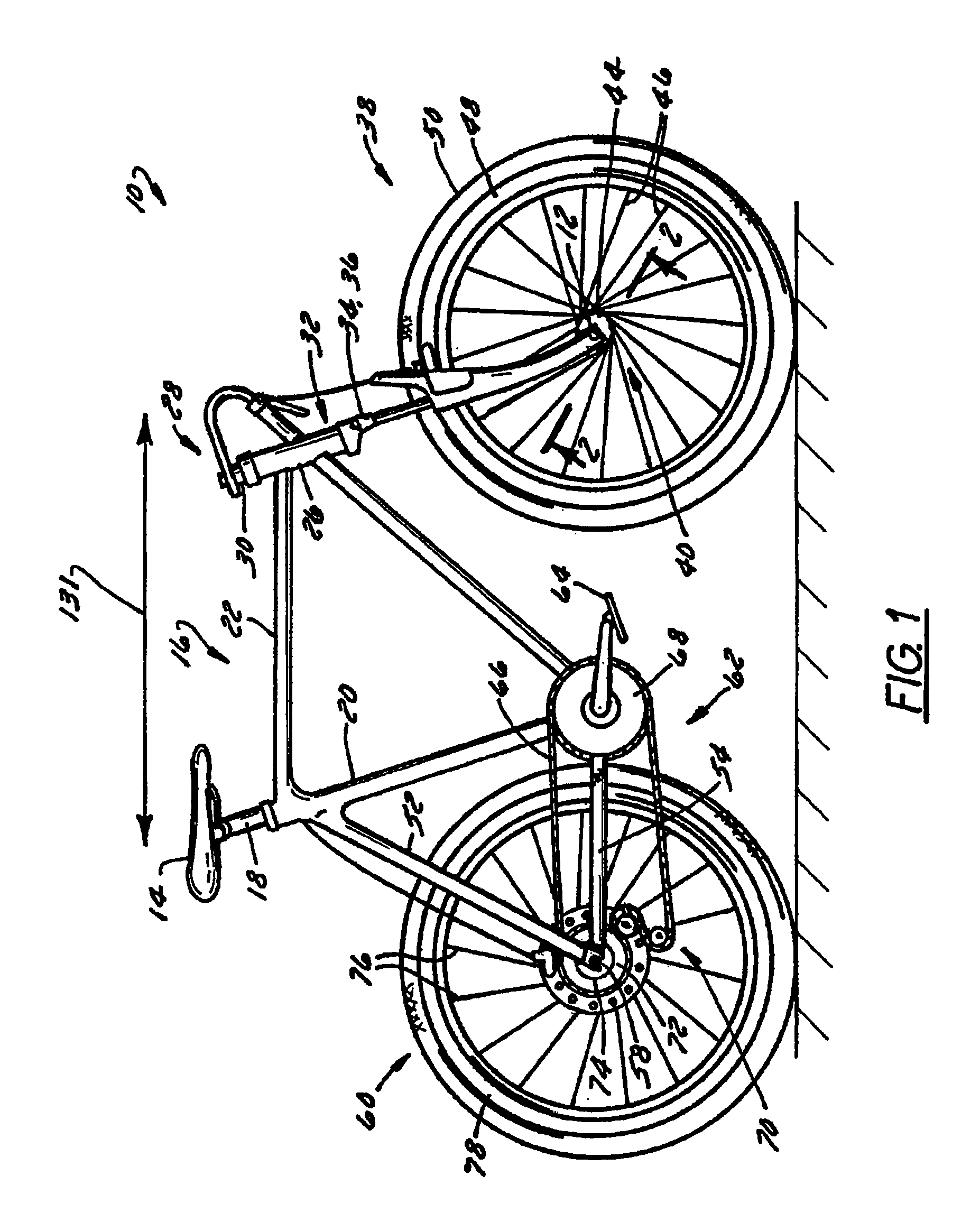
[0027]FIG. 1 shows a bicycle 10 equipped with a wheel quick release assembly 12 according to the present invention. Bicycle 10 includes a seat 14 that is slidably attached to a frame 16. A seat post 18 is connected to seat 14 and slidably engages a seat tube 20 of frame 16. A top tube 22 and a down tube 24 extend forwardly from seat tube 20 to a head tube 26 of frame 16. A handlebar or handlebar assembly 28 is connected to a stem tube 30 that passes through head tube 26 and engages a fork crown 32. The position of handlebar assembly 28 is fixed relative to stem tube 30 and fork crown 32 such that handlebar assembly 28 and fork crown 32 rotate together relative to head tube 26.

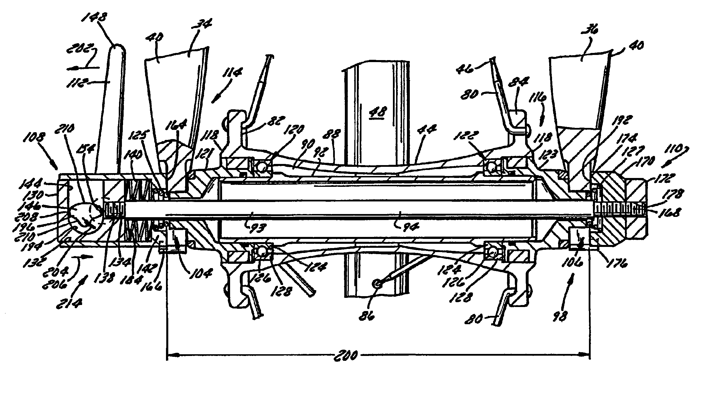
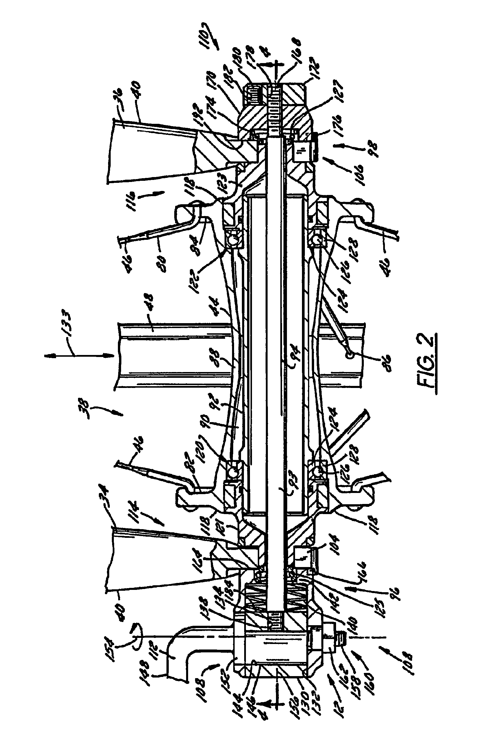
[0028]A pair of forks 34, 36 extend from generally opposite ends of fork crown 32 and are constructed to support a front wheel assembly 38 at an end of each fork or fork tip 40. Fork tips 40 cooperate with generally opposite sides of quick release assembly 12 so as to secure a hub 44 of front wheel assembly 38 ...


PUM


Abstract

A quick release assembly for a bicycle wheel that includes a pair of heads disposed at generally opposite ends of a skewer rod. One of the heads includes a cam surface that is translatable relative to the head. The quick release includes an operator having a handle portion and a stem portion. The stem portion includes a cam that cooperates with the cam surface formed in one of the heads such that operation of the handle alters the distance between the heads from a first orientation wherein the heads secure a wheel to a bicycle, a second orientation wherein the heads loosely secure the wheel to the bicycle and a third orientation wherein the wheel assembly can be freely removed from the bicycle.

Description

BACKGROUND OF THE INVENTION[0001]The present invention relates generally to bicycles and, more particularly, to a quick release assembly for securing a wheel to a bicycle such that the wheel can be removed and connected to a bicycle without the use of tools or the like.[0002]Traditionally, the wheels of a bicycle are secured to the frame via an axle or skewer rod that passes through a hub of the wheel and cooperates with corresponding structure of the frame. Occasionally, the wheel assemblies require servicing such as the changing of a tire or the like. It is readily appreciated that replacing a bicycle tire requires disengaging at least one side of the wheel assembly from the adjacent frame of the bicycle. Commonly, do in part to the awkwardness of manipulating a bicycle by a wheel, it is often more convenient to remove the wheel assembly entirely from the bicycle to perform such servicing. It is also readily appreciated that such service or repair activities are often presented at...

Claims


Application Information

Patent Timeline
Patent Type & Authority Patents(United States)
IPC IPC(8): B60B35/00
CPCB62K25/02B62K2206/00
Inventor CUSACK, DOUGLAS A.
Owner TREK BICYCLE CORPORATION
Why Eureka
Try Eureka