
Foot movement limiting device and shoe

a technology of foot movement and limiting device, which is applied in the field of foot movement dampers, can solve the problems of no protective effect at all, risk of injury when twisting the ankle, and damage to the ligaments of the ankle joint, and achieve the effects of reducing the absolute height of the shaft of the shoe, good protection of the foot movement damper, and high positional accuracy of the support elemen

Pending Publication Date: 2021-12-09
BETTERGUARDS TECH
View PDF5 Cites 1 Cited by
  • Summary
  • Abstract
  • Description
  • Claims
  • Application Information

AI Technical Summary

Benefits of technology

The patent text describes a shoe with a damping element that can move relative to the foot during movement. This allows for increased freedom of movement and comfort during activity. The shoe also has a window that allows for visual inspection and replacement of parts. The technical effect is increased flexibility, comfort, and ease of maintenance for a shoe with a damping element.

Problems solved by technology

When a defined inversion angle or a defined inversion speed or inversion acceleration is exceeded, damage to the ligaments of the ankle joint or tears can occur.
Such devices provide no protective effect at all before the limit angle is reached.
However, it is known that the risk of injury when twisting the ankle, particularly in the case of already weakened ligaments of after an injury, also depends significantly on the inversion or supination speed and the inversion or supination acceleration occurring during twisting, and not only on the inversion or supination angle.
In the range below the limit (inversion or supination) angle, such devices therefore provide no protection at all.
Moreover, after the limit angle is reached, the movement is completely blocked.
The abrupt stop of the twisting movement places a considerable load on the structure of the ankle joint, as a result of which there is an increased risk of injury, for example tearing at the bone or a cartilage injury.
On account of the considerable lever arm, the unfavourable introduction of force and the complexity of the knee joint, this can then lead to serious injuries, for example cruciate ligament tears or meniscal injuries, which, because of the way they restrict the person affected, and on account of their complexity and their limited healing, have much more negative consequences than an injury of the ankle joint.
However, the bar on the medial side of the foot still limits the freedom of movement of the ankle joint.
On account of the supporting and fixing means, these devices have a heavy weight and a relatively rigid structure and poor wearing comfort.

Method used


Image

  • Foot movement limiting device and shoe
  • Foot movement limiting device and shoe
  • Foot movement limiting device and shoe

Examples


Embodiment Construction

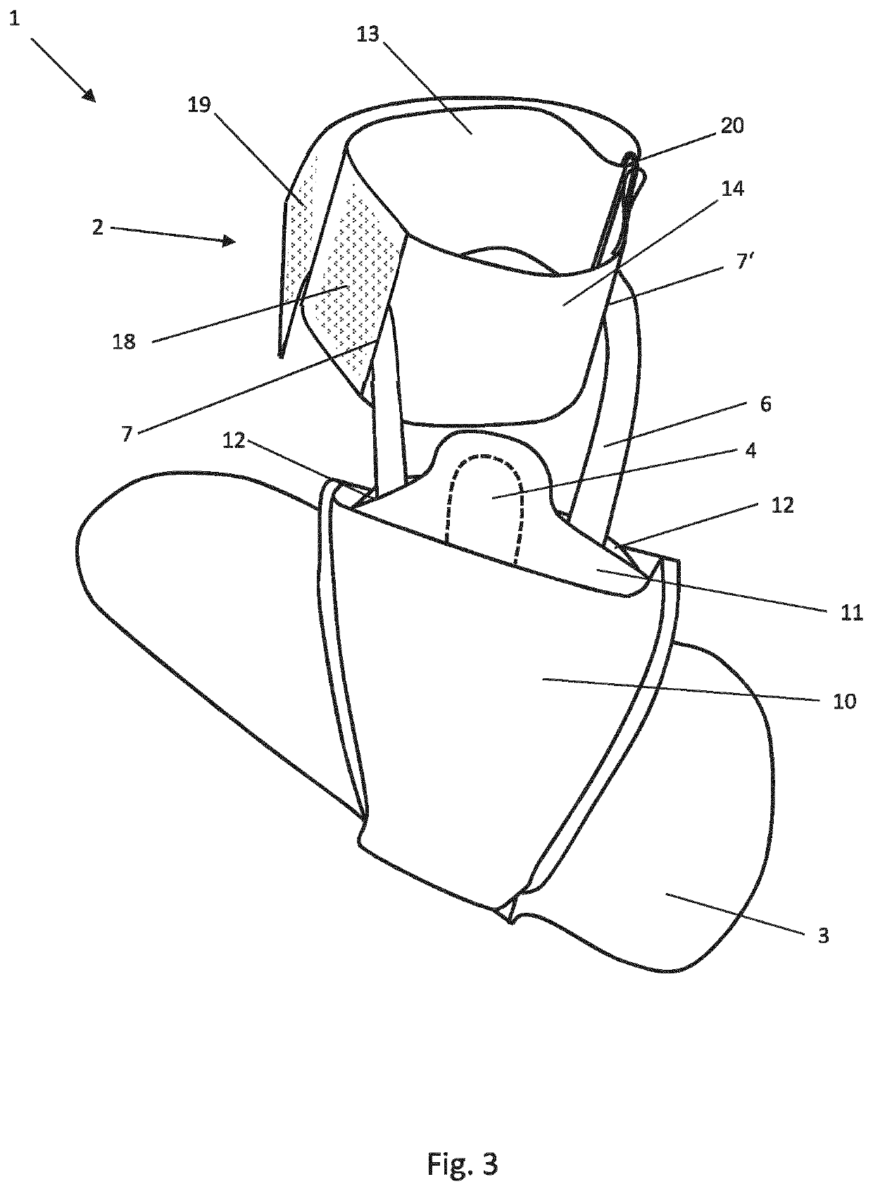
[0071]Illustrative embodiments are described below with reference to the figures. Elements that are identical or similar or that have an identical action are provided with identical reference signs in the different figures, and the description dispenses to some extent with repeated description of these elements in order to avoid redundancy.

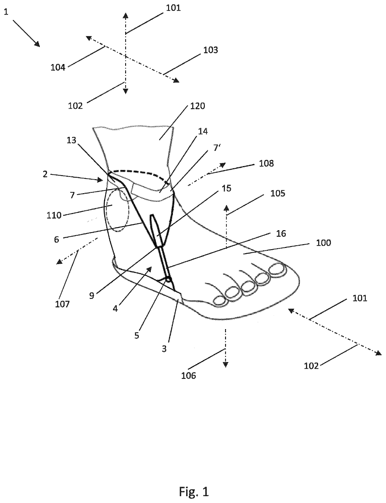
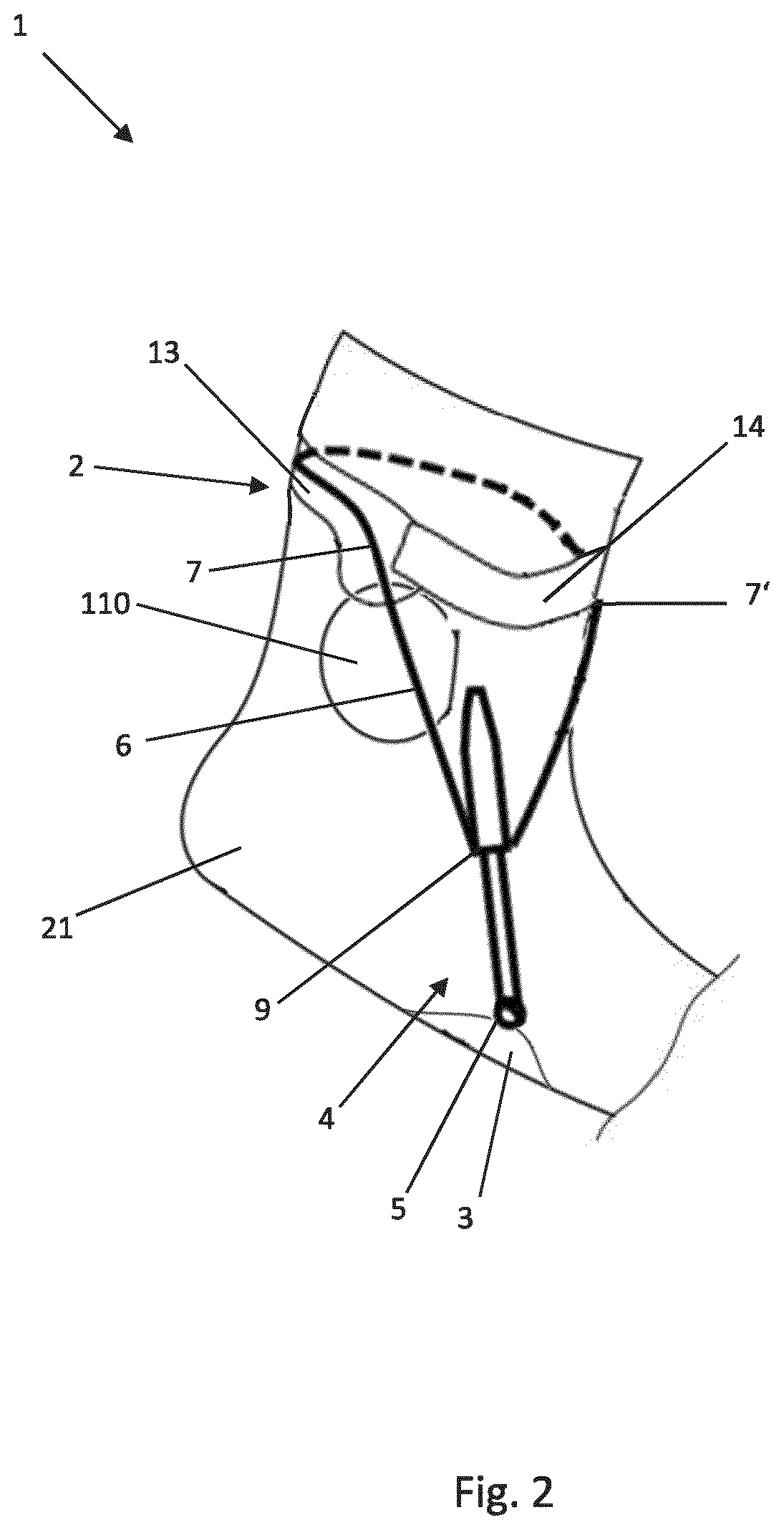
[0072]FIG. 1 shows a schematic perspective side view of a foot movement damper 1 for damping a foot movement via the ankle joint, according to a first embodiment, which is placed on a foot 100.

[0073]For better understanding, the reference signs 101-108 indicate the anatomical directions with respect to the ankle joint, and these apply analogously below in the description of the foot movement damper 1. Accordingly, the reference signs denote the following: 101 proximal, 102 distal, 103 posterior, 104 anterior, 105 dorsal, 106 plantar, 107 lateral and 108 medial.

[0074]The foot movement damper 1 has a support arrangement 2 for supporting from proxima...


PUM


Abstract

A foot movement damper for damping a foot movement via the ankle joint, and to a correspondingly configured shoe for damping a foot movement via the ankle joint. The foot movement damper includes a support arrangement for supporting on a lower leg or from proximally on the ankle bone, a retaining arrangement for retention on a foot, and a damping element for damping a relative movement between the support arrangement and the retaining arrangement

Description

TECHNICAL FIELD[0001]The present disclosure relates to a foot movement damper for damping a foot movement via the ankle joint, and to a correspondingly configured shoe for damping a foot movement via the ankle joint.DESCRIPTION OF THE RELATED TECHNOLOGY[0002]It is known to stabilize the movement of the ankle joint by means of devices for limiting foot movements, in order to counteract trauma caused by an ankle sprain, that is to say a movement of the ankle joint over at least one of its ankle joint axes in a non-physiological range. The most frequent form of sprain injury is an ankle joint distortion as a stretching or tearing following an inversion. On account of the increasing inversion angle, inversion movements over an ankle joint axis result in a change of the distance between foot and lower leg. When a defined inversion angle or a defined inversion speed or inversion acceleration is exceeded, damage to the ligaments of the ankle joint or tears can occur.[0003]To prevent this, ...

Claims


Application Information

Patent Timeline
Patent Type & Authority Applications(United States)
IPC IPC(8): A43B7/14
CPCA43B7/14A43B7/20A61F5/0111A61F5/0127A61F2005/0169A61F2005/0165
Inventor BICHLER, VINZENZSTUMPER, TIMOBUSCHINGER, OSCAR
Owner BETTERGUARDS TECH
Learn More