
Arrangement of a planetary gearset in a transmission

a technology of planetary gearsets and transmissions, applied in the direction of gearing elements, toothed gearings, gearings, etc., can solve the problems of greater assembly and maintenance costs and effor

Inactive Publication Date: 2009-03-12
ZF FRIEDRICHSHAFEN AG
View PDF1 Cites 1 Cited by
  • Summary
  • Abstract
  • Description
  • Claims
  • Application Information

AI Technical Summary

Benefits of technology

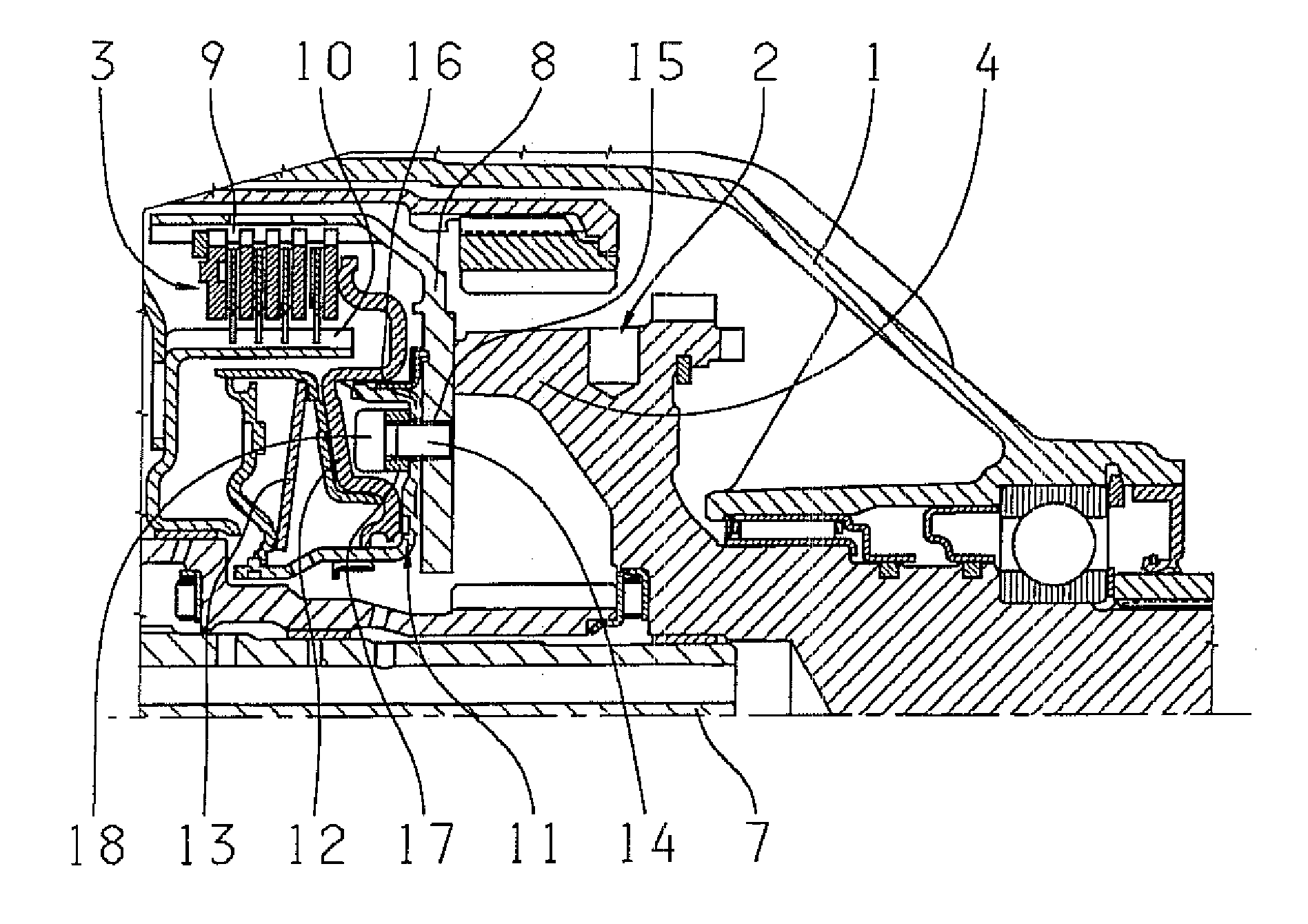
[0006]An arrangement of a planetary gearset with an axially adjacent shift element in a housing of a transmission is proposed in which the planetary gearset is connected to the shift element for torque transfer. The connection can be released without destroying the components concerned or to be joined together.
[0007]Thanks to the non-destructively detachable connection between the shift element and the gearset, the possibility is provided of retrofitting individual components of the shift element and the planetary gearset, even as far as dismantling the planetary gears. In this way, costs related to waste can be reduced considerably by replacing only the defective components. In addition, recycling of the transmission is made much simpler with the arrangement.
[0008]In a possible embodiment of the present invention, a clutch actuated hydraulically by a cylinder can be provided as the shift element. This is connected to a guide plate or carrier plate of the planetary gear carrier of the adjacent planetary gearset so that the connection can be taken apart without destroying the components to be joined. Thus, the shift element can be removed again from the adjacent planetary gear carrier without destroying either of them.
[0010]When dismantling is desired, the cylinder can be separated again from the planetary gear carrier simply by unscrewing the screw-bolt. Preferably, in the design described above a washer element or suchlike can be provided between the bolt head and the bottom area of the cylinder so as to increase the clamping length of the screw joint.
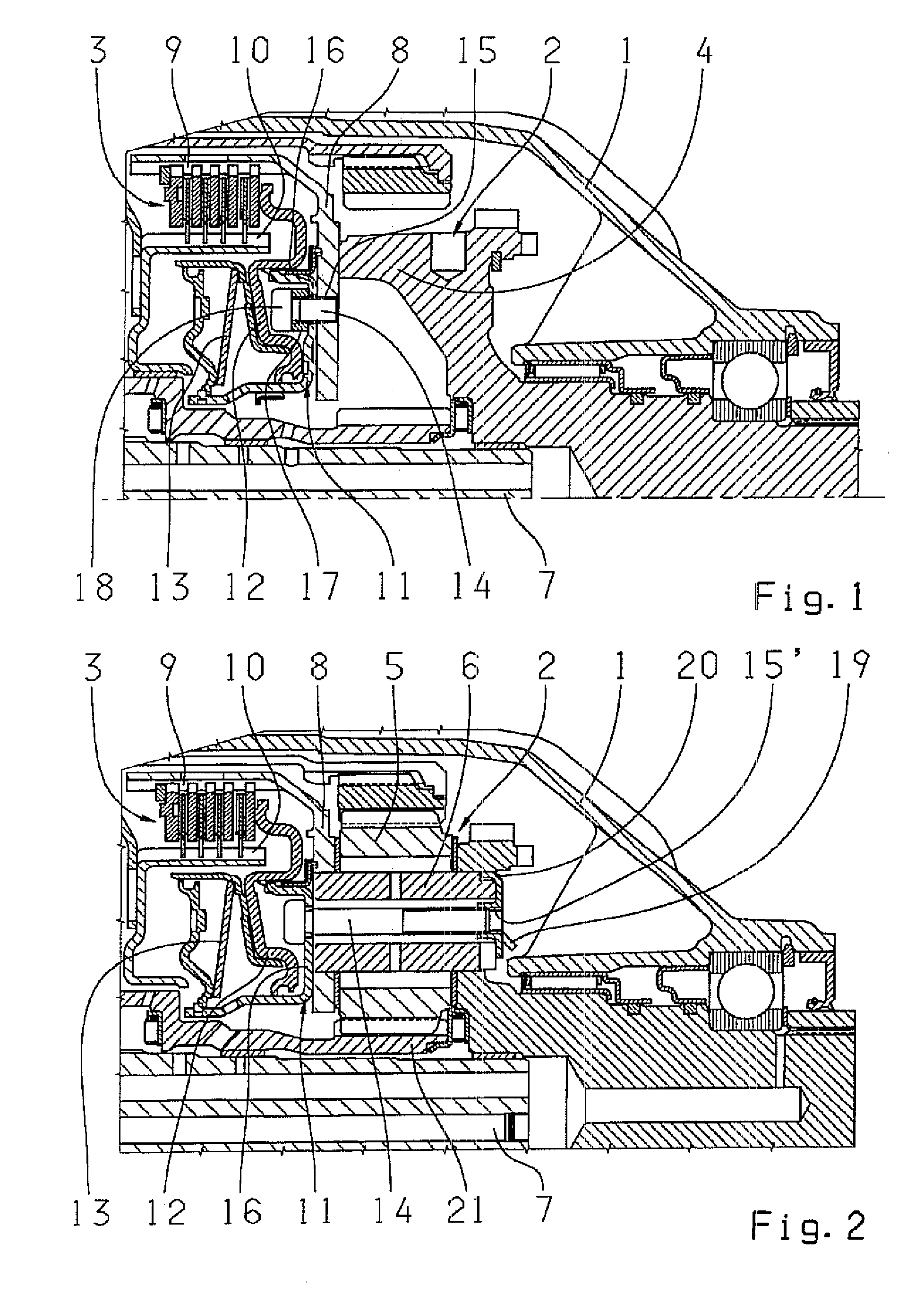
[0012]A further development can provide that the annular element has a way to secure it against rotation so that the screw attachment of the screw-bolts in the annular element is ensured. Moreover, it can be advantageous for the annular element to be made springy. In this way, any play between the contact surface on the planetary bolt and the contact surface on the drive output shaft can be compensated. Since the lubrication bore in the drive output shaft and the sun gear shaft of the planetary gearset and the oil collector plate on the sun gear shaft can be omitted, the design of the annular cylinder in the area of the lubrication oil feed for the planetary bolts can be simpler.
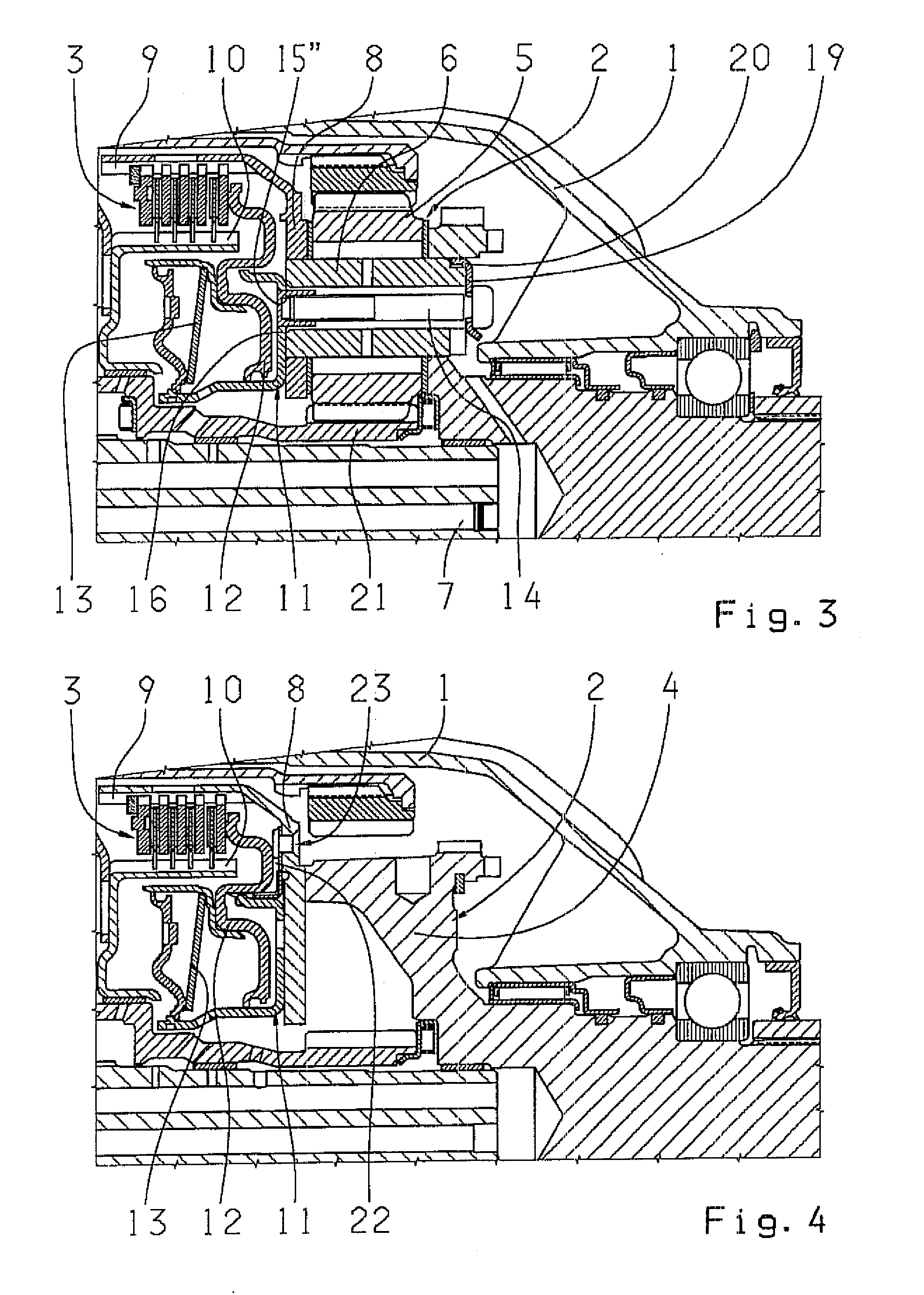
[0014]In another embodiment of the invention, instead of a screw joint a rivet joint can be provided between the annular cylinder and the guide plate. For this purpose, the cylinder can be enlarged radially outward, so that this area can be joined to the guide plate by at least one rivet or suchlike. To separate the cylinder from the drive output shaft or the planetary gear carrier, it is only necessary to drill out the rivet. This does not damage the components concerned, which can be re-used.

Problems solved by technology

This leads to greater assembly and maintenance cost and effort with the known arrangement.

Method used


Image

  • Arrangement of a planetary gearset in a transmission
  • Arrangement of a planetary gearset in a transmission
  • Arrangement of a planetary gearset in a transmission

Examples


second embodiment

[0027]FIG. 2 shows the arrangement in which the screw joint is formed through the planetary gear bolt 6 of the planetary gear carrier 4. For this, the screw-bolt 14 is again passed from the clutch side through the bore in the bottom area 16 of the annular cylinder 11 and along a further bore through the planetary gear bolt 6, to be screwed into a separate annular element 19 on the side remote from the clutch. The annular element 19 again has an internal thread 15′ into which the screw-bolt 14 can be screwed.

[0028]By virtue of the shape of the annular element 19, it also serves as an oil collection plate. In addition, the annular element 19 has an angled portion 20 which acts to secure the planetary bolt 6 rotationally. In this design version, the flow of lubrication oil takes place through a bore in the drive output shaft 7 and an oil outlet groove in the transmission housing 1. The annular element 19 is made to be springy. In this way, any play between the contact surface on the pl...

fourth embodiment

[0030]FIG. 4 shows a fourth embodiment variant of the arrangement. In this embodiment, a riveted joint is provided as the connection between the shift element and the planetary gearset 2. For this purpose, the annular cylinder 11 is enlarged radially outward by a corresponding extension 22. By means of this extension 22, the annular cylinder 11 is riveted to the guide plate 8. To release the annular cylinder 11 from the output shaft 7 or the planetary gear carrier 4 again, a rivet 23 can be drilled out. This damages neither of the components to be joined, which can be re-used after dismantling.

[0031]FIG. 5 shows a fifth embodiment of the arrangement, which is based on the first embodiment shown in FIG. 1. In contrast to FIG. 1, an internal thread 15′″ is this time made in the guide plate 8 for the screw-bolt 14 as a through-going thread or threaded bore. In this case the planetary gear carrier 4 has a recess 24 to allow the screw-bolts 14 to be fitted. No washer is needed between th...


PUM


Abstract

An arrangement is proposed for a planetary gearset (2) with an axially adjacent shift element in a housing (1) of a transmission of a vehicle, such that the planetary gearset (2) is connected to the shift element for torque transfer, and such that a non-destructively detachable connection is provided between the shift element and the planetary gearset (2).

Description

[0001]This application claims priority from German Applicatio Serial No. 10 2007 042 714.1 filed Sep. 7, 2007.FIELD OF THE INVENTION[0002]The present invention concerns an arrangement of a planetary gearset with an axially adjacent shift element in a housing of a transmission.BACKGROUND OF THE INVENTION[0003]From automotive technology, an arrangement of a planetary gearset with an axially adjacent shift element, as components of an automatic transmission of planetary design for a motor vehicle, is known. A planetary gear carrier of a planetary gearset comprises a number of planetary gears mounted on the planetary gear carrier by way of planetary gear bolts. For this, the planetary gear carrier comprises at least one carrier plate or guide plate by which the planetary gearset is connected to the adjacent shift element for torque transfer.[0004]The shift element axially adjacent to the planetary gearset is made as a clutch, which is actuated by an annular cylinder that co-operates wit...

Claims


Application Information

Patent Timeline
Patent Type & Authority Applications(United States)
IPC IPC(8): F16H3/44
CPCF16H3/66F16H63/3026F16H57/08
Inventor HOCKL, GERHARD
Owner ZF FRIEDRICHSHAFEN AG
Learn More