Quick release connector device

a connector and quick release technology, applied in the direction of coupling device connection, engagement/disengagement of coupling parts, electrical apparatus, etc., can solve the problems of difficult disengagement of locking ring, inability to stably retain the sealing ring between the two connector elements, and difficulty in disengaged locking ring, etc., to achieve quick disengagement from each other and quick coupling

Active Publication Date: 2010-05-25
ALINER INDS
View PDF8 Cites 19 Cited by
  • Summary
  • Abstract
  • Description
  • Claims
  • Application Information

AI Technical Summary

Benefits of technology

[0008]The primary objective of the present invention is to provide a connector device including two connector elements to be quickly coupled together and to be quickly disengaged from each other when required.

Problems solved by technology

However, after the locking ring is engaged with the second connector element, it will be difficult to disengage the locking ring from the second connector element such that the two connector elements may not be easily and quickly disengaged from each other when required.
In addition, the sealing ring engaged between the two connector elements may not be stably retained in place and may be moved relative to the two connector elements such that an air or water tight seal may not be suitably formed between the two connector elements.
Furthermore, the coupling member includes a complicated structure that may not be easily and quickly manufactured.

Method used


Image

  • Quick release connector device
  • Quick release connector device
  • Quick release connector device

Examples


Embodiment Construction

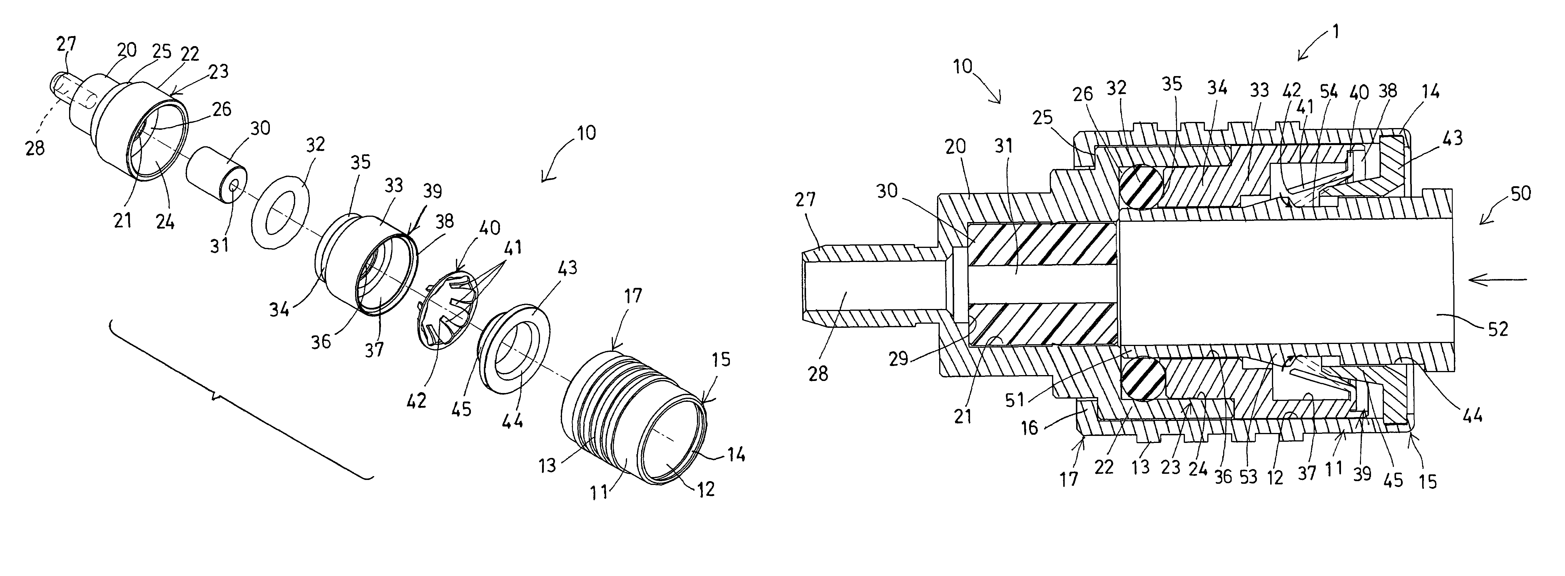
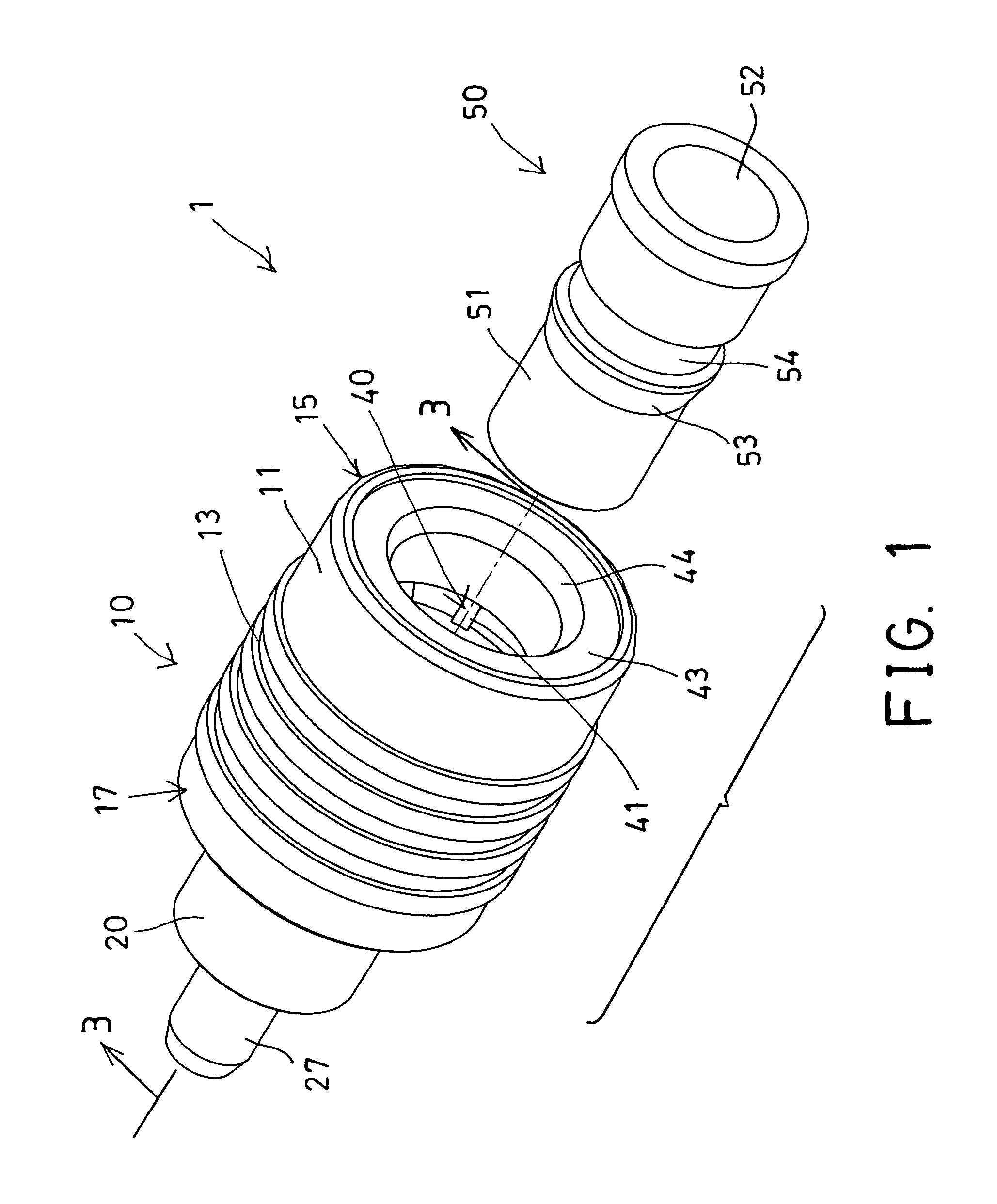
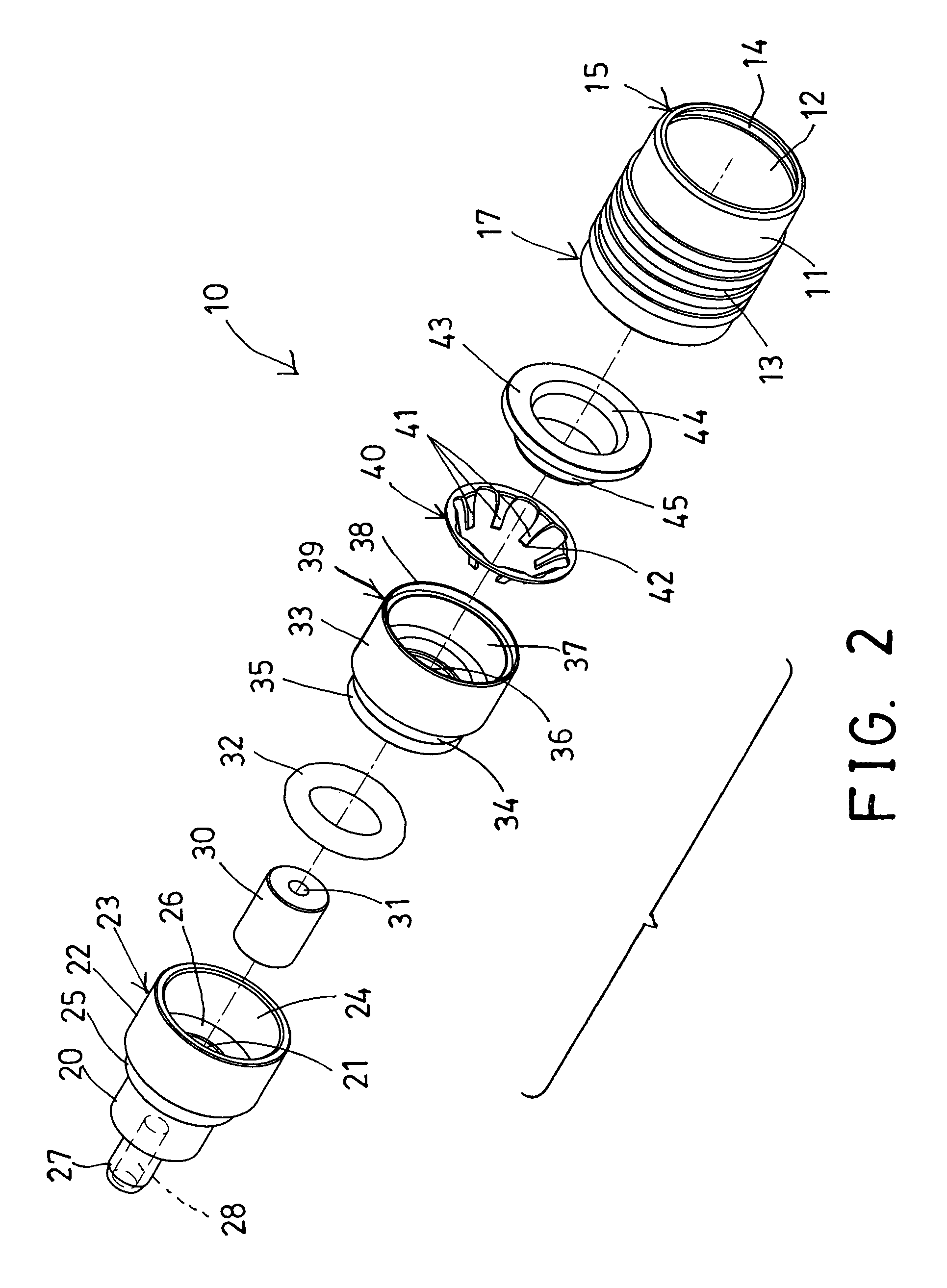
[0023]Referring to the drawings, and initially to FIGS. 1-4, a connector device 1 in accordance with the present invention comprises two connector elements 10, 50 to be selectively plugged or coupled together for electrically connecting or coupling two pairs of conductors (not shown) together, and to be selectively disengaged from each other when required. The first or female connector element 10 includes an outer shell or ferrule 11 having a chamber 12 formed therein and having a rough or serrated outer peripheral surface 13 formed thereon for allowing the ferrule 11 to be frictionally held or grasped by the user and for allowing the ferrule 11 to be easily moved by the user.

[0024]The ferrule 11 includes an annular or peripheral recess 14 formed in the inner portion at one end portion 15 thereof, and includes a peripheral flange 16 extended radially and inwardly from the other end portion 17 thereof. The first connector element 10 further includes a receptacle 20 having a compartme...


PUM


Abstract

A connector device includes a ferrule, a receptacle having a housing on one end and fitted in the ferrule for receiving an insulating member, a sealing ring fitted in the housing and engaged with the housing, a sleeve fitted in the ferrule and engaged with the housing and having a peripheral lip to engage with the sealing ring, a locking ring attached to the sleeve and having a number of blades, and an actuating member attached to the ferrule and having an actuator for moving the blades radially and for allowing a swelling of a tubular member to be moved over the blades and for allowing two connector element to be quickly coupled together and to be quickly disengaged from each other when required.

Description

BACKGROUND OF THE INVENTION[0001]1. Field of the Invention[0002]The present invention relates to a connector device, and more particularly to a quick release connector device including two connector elements to be quickly coupled together and to be quickly disengaged from each other when required.[0003]2. Description of the Prior Art[0004]Typical connector devices, such as electrical plug connectors, coaxial connectors, etc., comprise two connector elements to be selectively plugged or coupled together for electrically connecting or coupling two conductors together, and to be selectively disengaged from each other when required.[0005]For example, U.S. Pat. No. 6,709,289 to Huber et al. discloses one of the typical electrical plug connectors also comprising a first connector element and a second connector element to be connected or coupled together by means of a coupling member, and the connector elements each include an outer conductor and an inner conductor, and the coupling member...

Claims


Application Information

Patent Timeline
Patent Type & Authority Patents(United States)
IPC IPC(8): H01R13/627
CPCH01R13/6277H01R13/5202
Inventor YANG, CHUNG TAWU, MENG CHIEH
Owner ALINER INDS
Why Eureka
Try Eureka