Method and apparatus for laser drilling holes with tailored laser pulses

a laser pulse and laser drilling technology, applied in the field of laser processing a workpiece, can solve the problems of reducing the throughput of via formation, unsatisfactory heating effect of via structure, etc., and achieve the effect of reducing throughput, and reducing material removal tim

Inactive Publication Date: 2009-09-24
ELECTRO SCI IND INC
View PDF4 Cites 15 Cited by
  • Summary
  • Abstract
  • Description
  • Claims
  • Application Information

AI Technical Summary

Benefits of technology

[0008]In one embodiment via quality is improved by specifically tailoring the CO2 laser pulse into one with a power spike occurring at a certain time during the laser pulse at the beginning of the via formation. This tailored pulse with a spike is effective in explosively ejecting volume material out of the via site at high speed, so less debris will be formed around the area of the via, or less re-deposition back to the wall inside of the via. This tailored pulse shape will also allow the pulse rate to be increased over the rate used with prior art pulses, since the explosive ejection caused by the tailored pulse disperses the laser induced plume or plasma much faster than prior art pulses, allowing the next laser pulse to be fired at the substrate more quickly without forming debris. This is because the plume or plasma absorbs laser energy, resulting in an undesired heating effect on the via structure. The fact that the plasma absorbs laser energy preventing it from reaching the substrate will also reduce the via formation throughput. A high rate of energy coupling helps reduce smear, since it works to couple energy rapidly into the organic material attached to the metallic conductor and hence remove it before the metal can conduct the energy away in the form of heat. At a later stage of via drilling, laser pulse or pulses with different power profile can be used, such as one with a Gaussian shape and optimized peak power which is not necessarily the same as that of the pulses used in the other stages of the via drill to ensure that the bottom of the via will be cleaned out without having damage caused by smear, or delamination (separation of the conducting material and insulating material around the bottom area). The total laser energy applied to the substrate must be controlled to prevent damage to the surrounding material or the metallic conductor at the bottom of the via. This is accomplished by controlling the tailored pulse shape and the total numbers of tailored and non-tailored pulses.
[0009]A tailored pulse is defined as a laser pulse which has a leading edge, a falling edge and at least one power spike in between. Some examples of tailored pulses of this type are shown schematically in FIGS. 4 and 5. These figures graph instantaneous laser power vs. time. Tailored pulses 160, 180 are characterized by a leading edge 162, 182 a falling edge 164, 184 and power spikes 166, 186. These power spikes serve to rapidly couple energy into the material to be removed without increasing the total energy delivered to the substrate beyond a point where damage would occur.
[0013]FIGS. 4 and 5 also show the use of incubation pulses 168188 before and after tailored pulses 160, 180 and non-tailored pulses 170, 190, and 192. These pulses serve to pre-heat the material to enable the succeeding pulses to more easily remove material. Pre-heating raises the temperature of the material without causing damage to the surrounding substrate. Pre-heat pulses are below the threshold that would permit material removal. The subsequent tailored or non-tailored pulses can then begin removing material more rapidly and with better quality since the material already has energy stored in it from the pre-heat pulses.

Problems solved by technology

This is because the plume or plasma absorbs laser energy, resulting in an undesired heating effect on the via structure.
The fact that the plasma absorbs laser energy preventing it from reaching the substrate will also reduce the via formation throughput.

Method used


Image

  • Method and apparatus for laser drilling holes with tailored laser pulses
  • Method and apparatus for laser drilling holes with tailored laser pulses
  • Method and apparatus for laser drilling holes with tailored laser pulses

Examples


Embodiment Construction

[0025]Efficiently drilling high-quality vias involves removing substantially all insulating material from the via volume with the fewest laser pulses while avoiding damage to the surrounding substrate. This can be accomplished by drilling a via with one or more tailored pulses possibly in combination with incubation pulses and non-tailored pulses as described herein. Three measurements of pulses are relevant to via drilling. The first is peak power, expressed in Watts, which measures the highest instantaneous power reached during the pulse duration. The second is energy, which is calculated by integrating power over the duration of the pulse. When the beam spot size is included into the consideration, term of fluence is more often used which is in a unit of Joules / cm2, The third one is the profile of the power. It is the rate of how fast the laser energy is applied to the via site versus time.

[0026]Maximum laser pulse fluence is determined by the damage threshold of the substrate be...


PUM

PropertyMeasurementUnit
response timeaaaaaaaaaa
wavelengthsaaaaaaaaaa

Abstract

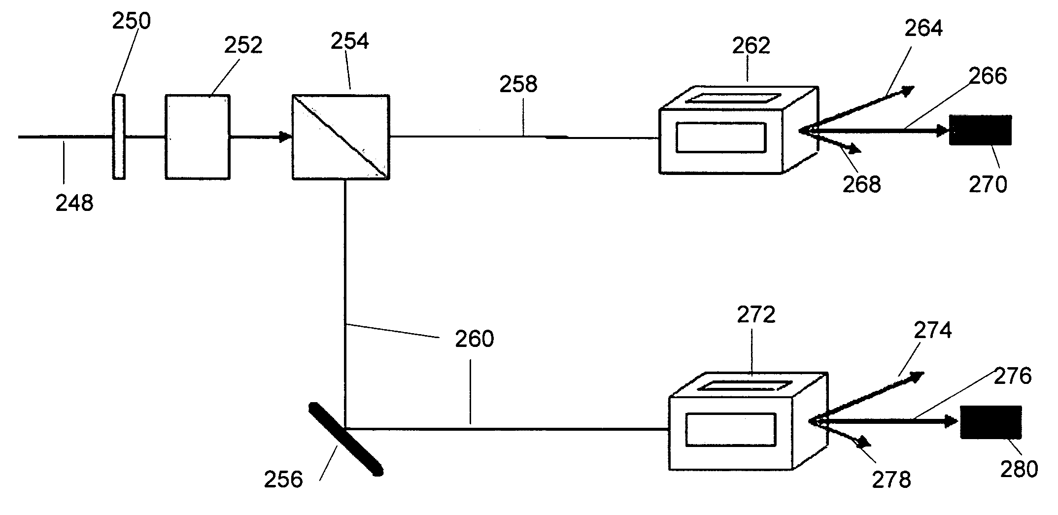
An improved method and apparatus for drilling vias in electronic substrates with laser pulses is presented which uses one or more tailored pulses to reduce debris remaining in the via while maintaining system throughput and avoiding damage to the substrate. A tailored pulse is a laser pulse that features a power spike having a peak power 10% higher than the average power of the pulse and lasting less than 50% of the duration of the pulse. Methods and apparatuses for creating tailored pulses by slicing longer duration pulses are shown.

Description

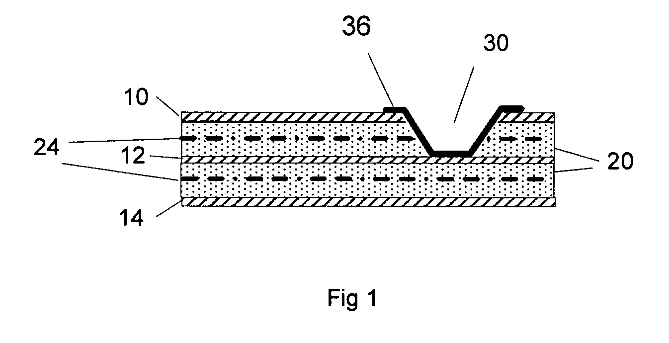
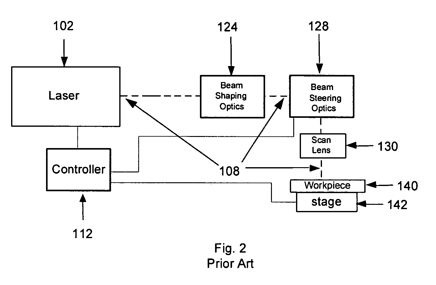
TECHNICAL FIELD[0001]The present invention relates to laser processing a workpiece. More particularly, it relates to a method and apparatus for laser drilling holes in multilayer electronic substrates or boards for the purpose of forming vias to permit electrical interconnections between the layers using pulses from a CO2 laser. Specifically, it relates to laser drilling holes in a workpiece with tailored pulses created from a longer duration pulse using pulse slicing techniques.BACKGROUND OF THE INVENTION[0002]Nearly all currently manufactured electronic products, including devices such as computers, cell phones and other consumer electronics, are constructed by attaching electronic components to substrates or boards (hereafter as substrates). Electronic components include integrated circuits, discreet active and passive devices, displays and connectors. Substrates function to hold the electronic components in place and provide electrical connections between the components with des...

Claims


Application Information

Patent Timeline
Patent Type & Authority Applications(United States)
IPC IPC(8): B23K26/38
CPCB23K26/063B23K26/381H05K3/0035B23K26/385B23K26/409B23K26/402B23K26/4065B23K26/4075B23K26/408B23K26/401B23K26/40B23K26/0622B23K26/382B23K26/389B23K2103/54B23K2103/10B23K2103/12B23K2103/172B23K2103/42B23K2103/50B23K2103/52B23K2103/08
Inventor SUN, YUNLONGLEI, WEISHENGMATSUMOTO, HISASHIJOHANSEN, BRIANHARDY, GREGGBAIRD, BRIAN
Owner ELECTRO SCI IND INC
Why Eureka
Try Eureka