Method and apparatus for providing light having a selected polarization with an optical fiber

a technology of optical fiber and polarization, applied in the field of optical devices, can solve the problems of insufficient power output of available optical fiber lasers and amplifiers, inability to operate over the wide range of wavelengths available from other types of lasers or amplifiers, and inability to efficiently convert wavelengths, etc., to achieve the effect of increasing bend loss and increasing bend loss

Active Publication Date: 2010-05-25
NUFERN
View PDF32 Cites 15 Cited by
  • Summary
  • Abstract
  • Description
  • Claims
  • Application Information

AI Technical Summary

Benefits of technology

[0010]In one aspect, the invention provides an optical apparatus for providing light having a selected linear polarization having a selected polarization ratio. As used herein, “light” is meant to include all electromagnetic radiation, whether visible or not, that those of ordinary skill in the art would recognize can be used in connection with the invention. In one embodiment, an apparatus according to the invention can comprise a length of optical fiber. The fiber can have a core and a cladding disposed about the core. The fiber can comprise a rare earth for providing light having a first wavelength responsive to receiving pump light having a second wavelength that is different than the first wavelength. If the length of optical fiber were placed in a first position wherein the length of fiber is substantially linearly oriented, the fiber could propagate (e.g., at the first wavelength) a fundamental mode and at least one higher order mode, such as, for example, a plurality of higher order modes, and the apparatus could provide light having a first polarization ratio for light of the selected linear polarization and an M2 parameter. In one embodiment, the fiber is positioned in a second position that increases the bend loss in the fiber relative to said first position such that, responsive to the increased bend loss, the apparatus can provide light having a reduced M2 parameter relative to the M2 parameter as well as a second polarization ratio for the selected linear polarization that is increased relative to the first polarization ratio, the second polarization ratio being at least 6 dB greater that the first polarization ratio. When the fiber is in the second position the apparatus can provide a slope efficiency that is at least 50% of the ratio of the second wavelength to the first wavelength.
[0017]In yet another aspect of the invention, Applicants have discovered that an optical fiber device, such as, for example, a laser, can provide light having a desired polarization (e.g., substantially linearly polarized) and good beam quality by appropriately positioning an optical fiber, including a fiber that comprises an active material (e.g., a rare earth), to induce bend loss that attenuates one polarization (e.g., the polarization along the fast axis of a polarization maintaining (PM) fiber) more than another polarization (e.g., polarization along the slow axis), such that one or both of good slope efficiency and a good polarization ratio (e.g., the ratio of the power of light in desired polarization (e.g., light polarized along the slow axis) to the power of light in the undesired polarization (e.g., light polarized along the fast axis). Applicants have more particularly discovered that the foregoing technique works well when the fiber is a Large Mode Area (LMA) fiber (used herein to indicate a fiber having a core having a diameter of greater than 15 microns and a numerical aperture of the core relative to its cladding of less than 0.1), and that higher order modes as well as one of the polarizations of the fundamental mode are attenuated such that device can provide light having good beam quality (e.g., a low M2 parameter) and substantially linear polarization (e.g., a good polarization ratio). LMA fibers have become popular for power scaling fiber lasers (see for example F. Di Teodoro, J. P. Koplow, S. W. Moore and D. A. V. Kliner, Optics Letters, v. 27, p 518, 2002) and amplifiers.
[0019]The invention can provide a simple technique that can avoid some of the more complex solutions upon which the prior art has focused. The invention can also be used as an amplified spontaneous emission (ASE) source, as well as a laser or amplifier or superfluorescent source.
[0021]The optical apparatus includes a second optical element in optical communication with the first length of optical fiber, wherein the second optical element receives light having a first polarization ratio. Polarization ratio can be defined as the ratio of light power having the first wavelength and the second polarization to light power having the first wavelength and the first polarization. The second optical element attenuates light having the first wavelength and the first polarization by a third amount and attenuates light having the first wavelength and the second polarization by a fourth amount that is less than the third amount and that is less than the second amount. The second optical element can provide light having a second polarization ratio that is larger than the first polarization ratio.
[0027]In one aspect, the invention provides a method of providing output light having a selected linear polarization, comprising providing a length of optical fiber comprising a rare earth for providing output light having a first wavelength responsive to receiving pump light having a second wavelength that is different than said first wavelength, where the fiber can support at the first wavelength a fundamental mode having first and second orthogonal linear polarizations and a plurality of higher order modes; bending the fiber so as to increase the bend loss of the higher order modes and the second linear polarization such that the fiber can provide output light having an improved beam quality in terms of M2 parameter and an improved polarization ratio for light having the first polarization relative to the second polarization; and refraining from introducing excessive bend loss for the first polarization such that the fiber can provide light including the first wavelength and the improved M2 parameter and polarization ratio at a slope efficiency of greater than 50% of the ratio of the second wavelength to the first wavelength.

Problems solved by technology

For example, a particular fiber laser or amplifier may not operate over the wide range of wavelengths available from other types of lasers or amplifiers.
In certain circumstances, available optical fiber lasers and amplifiers do not readily provide high enough power output.
The above noted process for converting wavelength is not always efficient, and higher power can be required.
Also, fiber lasers and amplifiers typically do not readily produce as much power as other types of lasers or laser amplifiers, such as bulk solid state devices, gas lasers, or diode lasers, which have gained acceptance in industrial settings such as welding and the like, in large measure due to the ability to provide high enough power.
Accordingly, the number of applications for which fiber lasers can be used is unduly limited, despite their many advantages.
Unfortunately, fibers having large core diameters can support multiple spatial (transverse) modes.
The presence of such modes tends to degrade the quality of the light provided by the fiber.
Existing techniques, however, can be considered unduly complex or expensive and impractical in certain applications.

Method used


Image

  • Method and apparatus for providing light having a selected polarization with an optical fiber
  • Method and apparatus for providing light having a selected polarization with an optical fiber
  • Method and apparatus for providing light having a selected polarization with an optical fiber

Examples


working examples

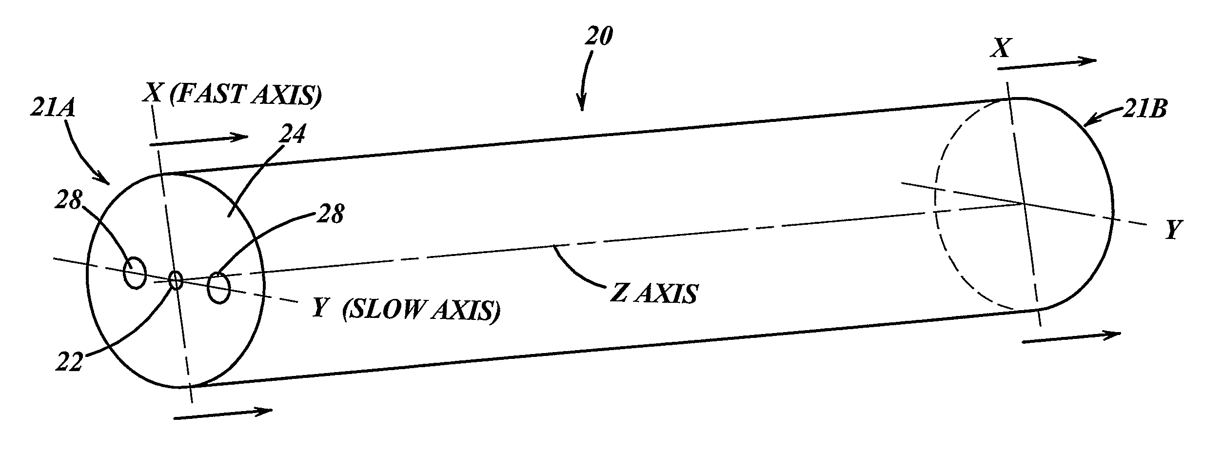
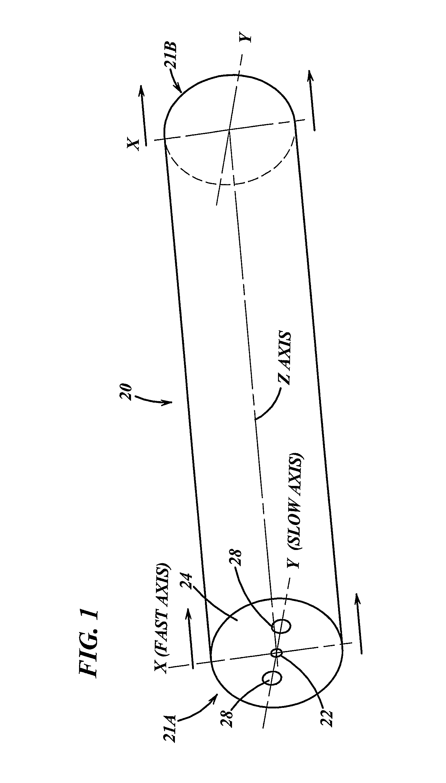
[0120]In this section, the design and fabrication of an optical fiber apparatus for providing a selected polarization of light is described, and experimental results presented. Because optical fibers that can handle higher powers are of principal interest, the apparatus described below used LMA fibers. The invention is not so limited, however, as is readily understood by one of ordinary skill in the art informed of the present specification. Experimental demonstration of an apparatus according to the present invention using PM-LMA optical fiber having a core diameter of 20 μm coil yielded a laser slope efficiency of ˜70% with a polarization ratio (PR)>10 dB, with the apparatus, which was configured as a laser, operating in substantially a single mode.

[0121]Two optical fibers are discussed, namely, Fiber A and Fiber B. Both fibers can be considered LMA fibers. Fiber A includes a core having a 20 μm diameter and a first cladding disposed about and adjacent the core and having a 400 μm...


PUM


Abstract

Optical apparatus (110, 500, 600, 800, 1000) for providing light having a selected linear polarization having a polarization ratio, the apparatus (110, 500, 600, 800, 1000) comprising a length of optical fiber (120, 504, 604, 804, 1001) comprising a rare earth for providing light having a first wavelength responsive to receiving pump light having a second wavelength that is different than said first wavelength, wherein if the length of optical fiber (120, 504, 604, 804, 1004) were placed in a first position between the length of fiber (120, 504, 604, 804, 1004) is substantially linearly oriented (20) the fiber (120, 504, 604, 804, 1004) could propagate at the first wavelength a fundamental mode and a plurality of higher order modes and the apparatus (110, 500, 600, 800, 1000) could provide light having a first polarization ratio for the selected linear polarization and an M2 parameter, and wherein the length of fiber (120, 504, 604, 804, 1004) is positioned in a second position that increases the bend loss of the fiber relative to the first position such that, responsive to the increased bend loss, the apparatus (110, 500, 600, 800, 1000) can provide light having a reduced M2 parameter as well as a second polarization ratio for the selected polarization that is increased relative to the first polarization ratio, the increase being at least 6 dB greater than the first polarization ratio, and wherein when the length of fiber (120, 504, 604, 804, 1004) is in the second position the apparatus (110, 500, 600, 800, 1000) can provide a slope efficiency that is at least 50% of the ratio of the second wavelength to the first wavelength.

Description

CROSS-REFERENCE TO RELATED APPLICATIONS[0001]This is a national stage application of PCT / US2005 / 002908, filed Jan. 31, 2005, which in turn claims priority to U.S. Provisional Patent Application No. 60 / 540,799, filed Jan. 30, 2004.FIELD OF THE INVENTION[0002]The present invention relates to optical devices, such as, for example, optical amplifiers, lasers and amplified spontaneous emission (ASE) sources, that can provide light having a selected polarization.BACKGROUND[0003]Optical fiber lasers and amplifiers can provide a flexible, rugged and simple source of light. It is often desirable that an optical fiber laser or amplifier can provide light having a selected polarization. Polarization refers to the direction of an electric field vector of a component of a propagating wave, and the selected polarization is typically specified as being present to a selected degree (e.g., a linear polarization can be specified as being present so as to have a selected polarization ratio to an ortho...

Claims


Application Information

Patent Timeline
Patent Type & Authority Patents(United States)
IPC IPC(8): H01S3/00
CPCG02B6/024G02B6/105G02B6/14H01S3/06712H01S3/06729H01S3/0675H01S3/094007H01S3/0941H01S3/1618
Inventor ABRAMCZYK, JAROSLAWMANYAM, UPENDRA H.SAMSON, BRYCE N.TANKALA, KANISHKA
Owner NUFERN
Why Eureka
Try Eureka