
Display pack and packaging method and apparatus

a technology of display packaging and packaging method, applied in the field of product packaging, can solve the problems of difficult control of seal quality, and inability to use heat-sensitive adhesives

Inactive Publication Date: 2010-06-01
WINTERBORNE
View PDF41 Cites 45 Cited by
  • Summary
  • Abstract
  • Description
  • Claims
  • Application Information

AI Technical Summary

Benefits of technology

The method results in packages that are more secure, aesthetically appealing, and stronger, enabling larger sizes and heavier loads, with improved consistency and environmental friendliness compared to conventional techniques.

Problems solved by technology

One disadvantage of this type of conventional packaging is that the hot melt glue is typically applied by hand, and thus the seal quality is often difficult to control due to, for example, the varying drying speed of the glue, the placement of the glue, etc.
Another disadvantage is that the corrugation of the cardboard is visible at some of the side edges of the finished packaging (see FIG. 6(c), a view of the bottom edge of the packaging of FIG. 6(a)), making the packaging aesthetically unappealing.
Heat sensitive adhesives have not been used in the first type of packaging because corrugated cardboard sheets are poor heat conductors, and heat applied to the outer side of the cardboard cannot easily reach the area between the two cardboard sheets where the heat adhesive material would be applied.
A disadvantage of the second type of conventional packaging is that it sometimes lacks sufficient structural strength.
The lack of physical strength also makes it difficult to make larger packages (e.g. larger than 10 by 15 inches), or to pack heavier items.

Method used


Image

  • Display pack and packaging method and apparatus
  • Display pack and packaging method and apparatus
  • Display pack and packaging method and apparatus

Examples


Embodiment Construction

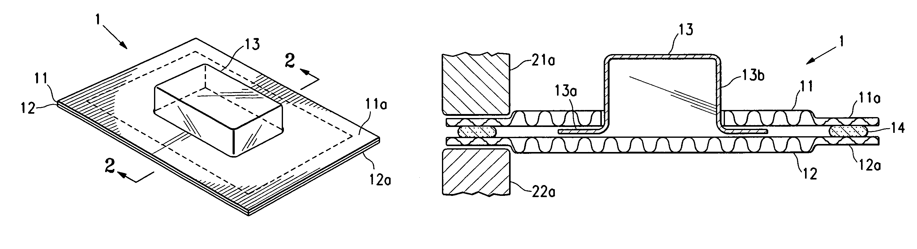
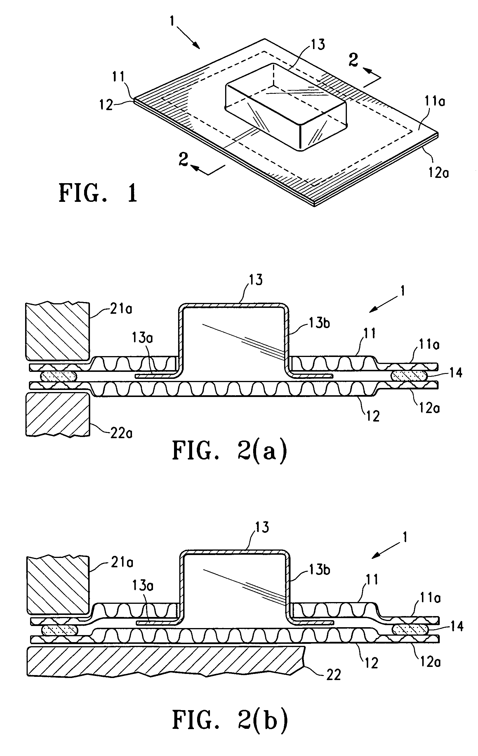
[0025]FIG. 1 shows a display pack according to an embodiment of the present invention which has an overall structure similar to that of a conventional packaging shown in FIG. 6(a) but is constructed differently. FIGS. 2(a) and 2(b) are cross-sectional views of the display pack of FIG. 1 along the line 2-2 (the differences between FIGS. 2(a) and 2(b) will be explained later). As shown in FIGS. 1, 2(a) and 2(b), the package 1 is made of two sheets of corrugated cardboard 11 and 12 and a plastic container 13 (preferably made of a clear plastic material such as PET) having a flat insertion portion 13a and a chamber portion 13b. The insertion portion is sandwiched between the two cardboard sheets 11 and 12, and the chamber portion 13b protrudes from the plane of the cardboard sheets via a cut on one cardboard sheet 11 and is used to hold the product inside. Although only one is shown in FIGS. 1, 2(a) and 2(b), a package may contain one or more plastic containers, and they may protrude fr...


PUM


Abstract

A display pack for a consumer product is made of two sheets of corrugated cardboard and a clear plastic container with a flat insertion portion sandwiched between the cardboard sheets. The two cardboard sheets are adhered together in a peripheral area of the package by a heat-sensitive adhesive, and the corrugations of the cardboard sheets are crushed and flattened in the peripheral area. To seal the package, the peripheral area of the two cardboard sheets is subject to sufficient pressure to crush the corrugations inside the cardboard sheets and flatten them in that area. Heat is applied to the outer side of the cardboard sheets in the peripheral area and conducted to the adhesive material between the two sheets to activate the adhesive material. A sealer machine with a heated sealing press or parallel sets of heated rollers may be used to carry out the sealing process.

Description

[0001]The present application is a continuation-in-part of U.S. Provisional Application No. 60 / 711,024, filed Aug. 24, 2005.BACKGROUND OF THE INVENTION[0002]1. Field of the Invention[0003]This invention relates to product packaging, and in particular, it relates to packaging for products suitable for store merchandising.[0004]2. Description of the Related Art[0005]A first type of conventional packaging for consumer products, shown in FIGS. 6(a) and 6(b) (which is a cross-sectional view along the direction of arrows 2-2), is made of two sheets of corrugated cardboard 101 and 102, and a clear plastic container 103 having a flat insertion portion 103a and a chamber portion 103b. The insertion portion is sandwiched between the two cardboard sheets 101 and 102, and the chamber portion 103b protrudes from the plane of the cardboard sheets via a cut (opening) on one cardboard sheet 101 and is used to hold the product inside. A second plastic container 103′ may be provided and protrudes fro...

Claims


Application Information

Patent Timeline
Patent Type & Authority Patents(United States)
IPC IPC(8): B65D81/24B31B50/62B31B50/64
CPCB65D73/0092B65B51/14B65D73/00
Inventor NAZARI, JOSEPH
Owner WINTERBORNE
Learn More