Paper feeder having hard nip and flexible nip

a feeder and flexible technology, applied in the field of feeders, can solve the problems of restricting paper thickness to single thickness, and achieve the effect of reducing downtime and quick installation

Active Publication Date: 2010-06-01
DMT SOLUTIONS GLOBAL CORP
View PDF3 Cites 6 Cited by
  • Summary
  • Abstract
  • Description
  • Claims
  • Application Information

AI Technical Summary

Benefits of technology

[0016]Thus, an important advantage is that a user need purchase only one sheet feeder even if the user has requirements for both thin and thick sheets of paper.
[0017]The sheet feeder includes a belt carriage and frame assembly upon which is mounted the transport belts, the separator wheels, and the fixed nip roller. Advantageously, the belt carriage and frame assembly is removably mounted to the frame so that a new belt carriage and frame assembly may be installed quickly, with minimal downtime, as needed. More particularly, the frame of the friction feeder includes a pair of parallel, laterally spaced apart channels that slidingly engage opposite ends of the belt carriage and frame assembly. A first clip, pivotally mounted to a first channel, releasably engages a first side of the belt carriage and frame assembly and a second clip, pivotally mounted to a second channel, releasably engages a second side of the belt carriage and frame assembly. The leading end of each clip is angled away from the leading end of its channel so that the clip is momentarily pivoted upwardly when the belt carriage and frame assembly is slid into the channels. Each clip then falls under the force of gravity into engagement with the belt carriage and frame assembly. It is therefore easy to pivot each clip out of engagement with its end of the belt carriage and frame assembly and slide an old belt carriage and frame assembly out of the channels and to slide a new one into the channels.

Problems solved by technology

Such structure restricts the feeder to handling sheets having a common thickness and said structure cannot impart a wave-like or other shape to the paper.
A major drawback of the known feeders that impart a wave into the paper being handled is that they are restricted to paper having only a single thickness.

Method used


Image

  • Paper feeder having hard nip and flexible nip
  • Paper feeder having hard nip and flexible nip
  • Paper feeder having hard nip and flexible nip

Examples


Embodiment Construction

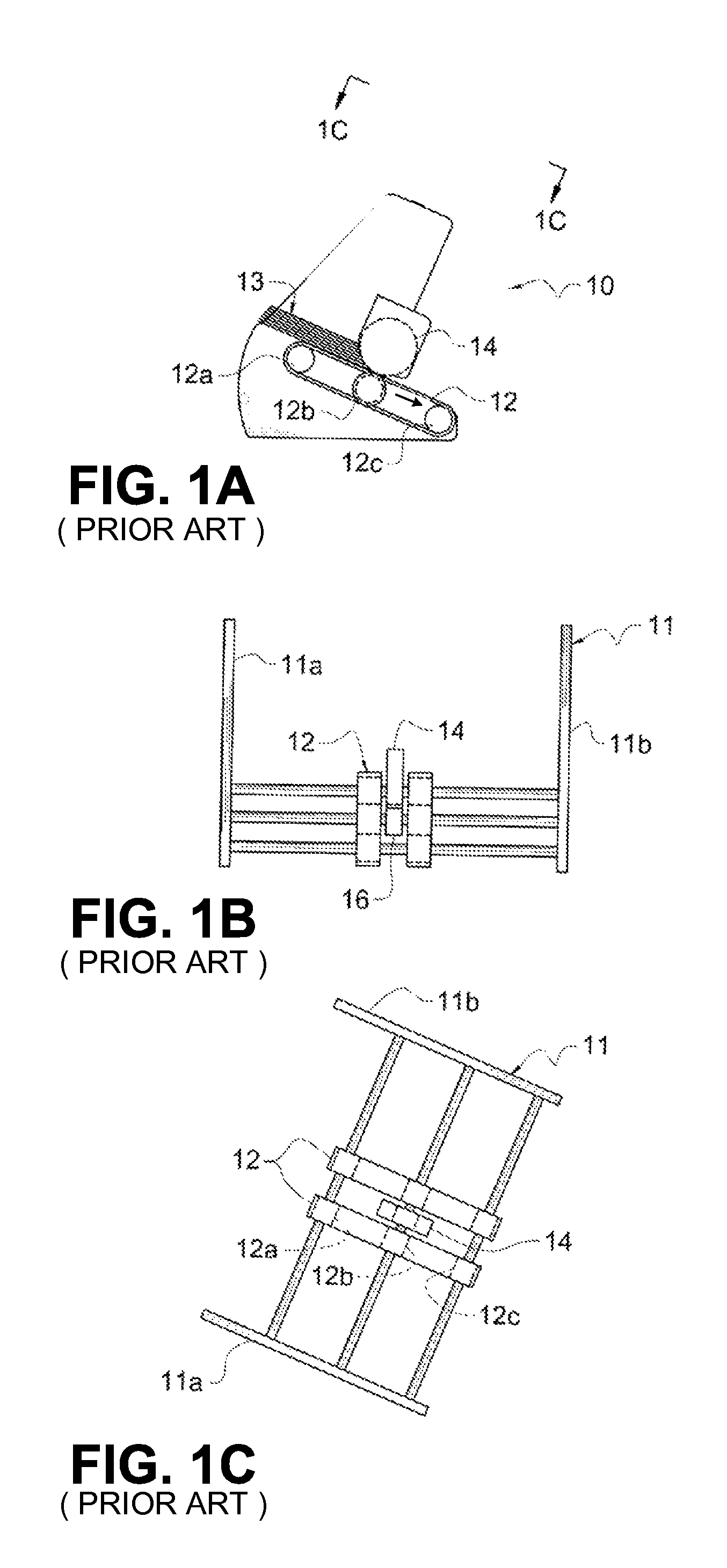
[0039]Referring now to FIGS. 1A, 1B, and 1C it will there be seen that a prior art sheet feeder apparatus in the field of this invention is denoted as a whole by the reference numeral 10.

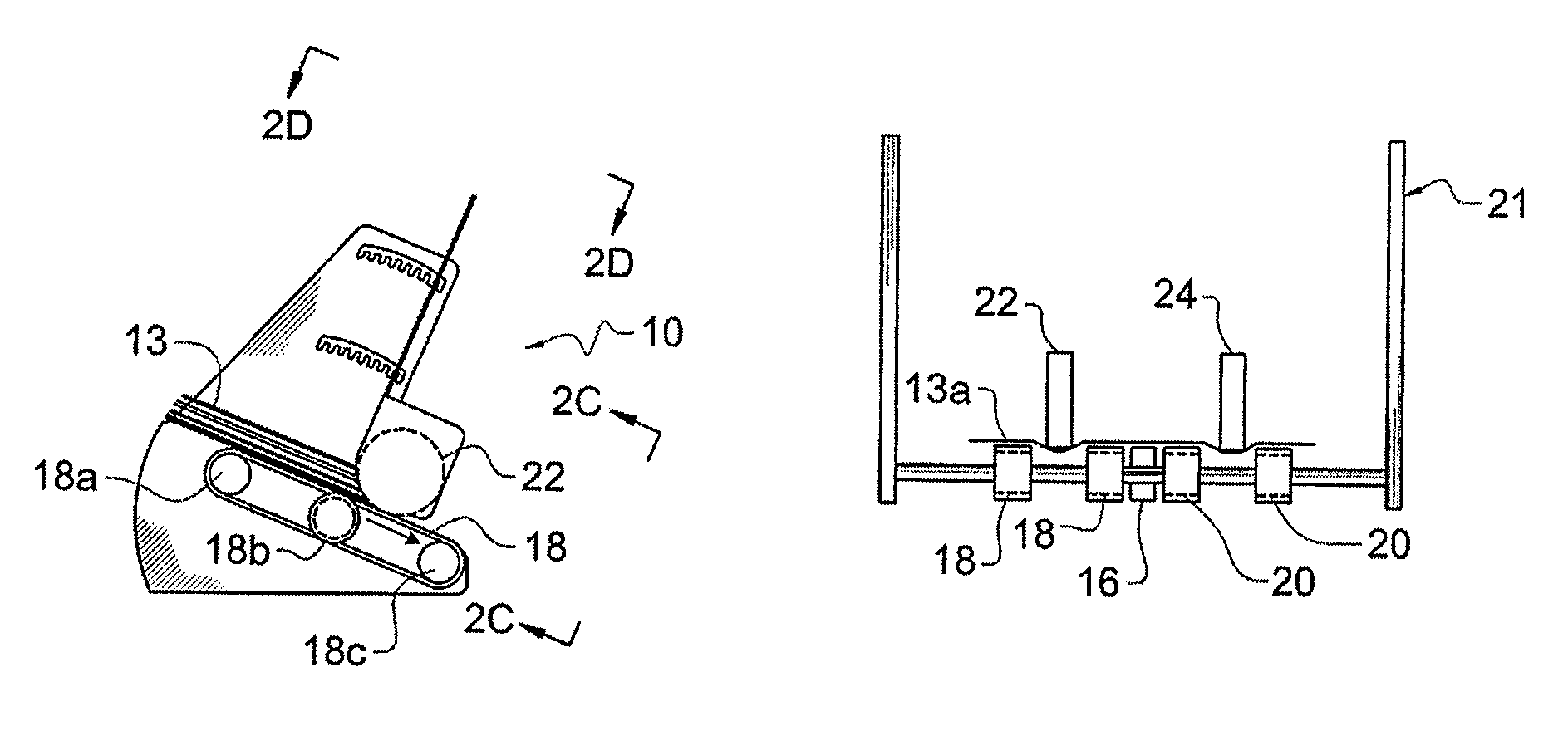
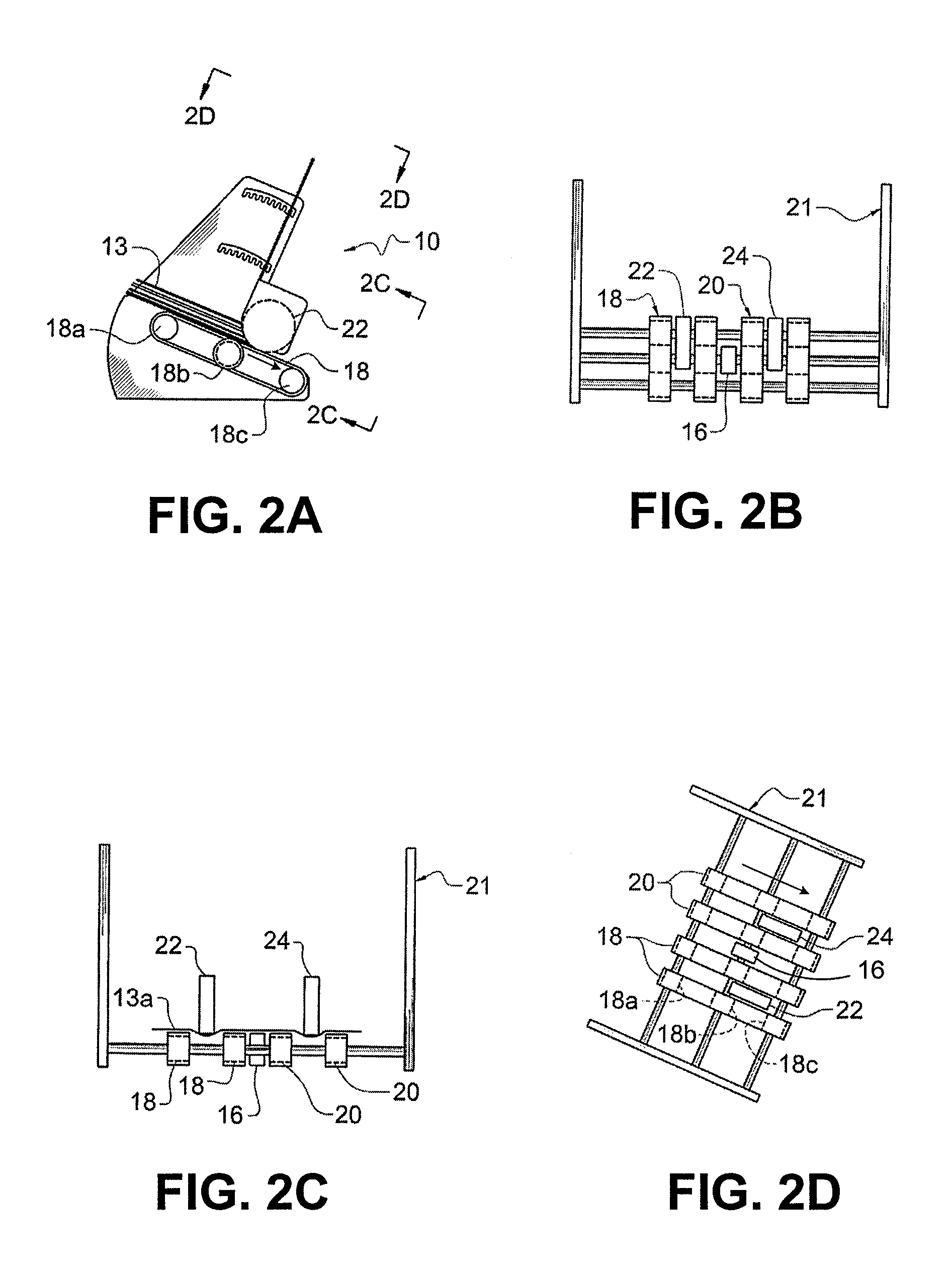
[0040]A pair of laterally spaced apart transport belts is denoted as a whole by the reference numeral 12 with arrow, a separator wheel is denoted 14, and a fixed nip roller is denoted 16. All of said parts are mounted on a belt carriage and frame assembly denoted 11 as a whole. Fixed nip roller 16 is positioned in confronting registration with separator wheel 14, said parts forming a hard nip point.

[0041]More particularly, belt carriage and frame assembly 11 includes a pair of frame arms 11a, 11b that are disposed in laterally spaced apart, parallel relation to one another. Assembly 11 forms an integral part of sheet feeder apparatus 10.

[0042]Transport belts 12 support from below and convey a sheet of paper passing through feeder 10. Fixed nip roller 16 also supports each sheet from below. Separator...


PUM

PropertyMeasurementUnit
thicknessesaaaaaaaaaa
speedaaaaaaaaaa
structureaaaaaaaaaa

Abstract

A friction feeder apparatus for handling sheets of paper of differing thicknesses includes a first plurality of laterally spaced apart transport belts positioned in underlying relation to the paper and a second plurality of laterally spaced apart separator wheels positioned in overlying relation to the paper. The transport belts are staggered with respect to the separator wheels. A sheet of paper passing through the feeder apparatus is undeflected from the top as it encounters the transport belts and is unsupported from the bottom as it encounters the separator wheels so that the sheet of paper is not held flat as it passes through the feeder but instead is forced into a wave-like, sinusoidal-like shape. In a first embodiment, the separator wheels are downstream of a fixed nip roller and in a second embodiment, the separator wheels are upstream of the fixed nip roller.

Description

FIELD OF THE INVENTION[0001]This invention relates, generally, to sheet feeder machines that handle paper. More particularly, it relates to a paper feeder that forms one or more troughs into each sheet of paper passing through it and that can handle papers of varying thicknesses.BACKGROUND OF THE INVENTION[0002]Companies that mail large numbers of paper items require high-speed paper-handling machines such as paper feeders that can handle thin sheets of paper as well as relatively thick paper such as paperboard, cardboard, and the like. It is sometimes advantageous to handle the paper while the paper is maintained in a flat configuration.[0003]In a typical prior art feeder, paper is supported from below and conveyed through the feeder by a plurality of rotatably-mounted laterally-spaced apart transport belts. A rotatably-mounted fixed nip roller is positioned between the transport belts, also supporting the paper from below, and a single rotatably-mounted separator wheel is position...

Claims


Application Information

Patent Timeline
Patent Type & Authority Patents(United States)
IPC IPC(8): B65H3/04
CPCB65H3/04B65H3/5284B65H2701/1916B65H2301/5122B65H2404/264B65H2301/42322
Inventor WERNER, TODD C.
Owner DMT SOLUTIONS GLOBAL CORP
Why Eureka
Try Eureka