
Common structure and door for multiple door electrical enclosure latching systems

a latching system and electrical enclosure technology, applied in the field of electrical enclosures, can solve the problems of different enclosures, different latching mechanisms, and additional costs in manufacturing, stocking and assembling

Inactive Publication Date: 2010-06-01
ROCKWELL AUTOMATION TECH
View PDF15 Cites 21 Cited by
  • Summary
  • Abstract
  • Description
  • Claims
  • Application Information

AI Technical Summary

Benefits of technology

The invention is a new electrical enclosure that has two latch plates, one for a door and one for a second configuration. The first latch plate has a hole for a latch pin, and the second latch plate has a rail and a rotating latching element. The latch plates can be easily inserted into the enclosure and used with either the door or the second configuration. This design allows for two types of latches to be accommodated in a simple and cost-effective manner.

Problems solved by technology

A drawback in the development of electrical enclosures has been the variety in the designs of the latching mechanisms.
For manufacturers, then, such variety leads to additional costs in manufacturing, stocking and assembling different enclosure structures to accommodate the different latches.

Method used


Image

  • Common structure and door for multiple door electrical enclosure latching systems
  • Common structure and door for multiple door electrical enclosure latching systems
  • Common structure and door for multiple door electrical enclosure latching systems

Examples


Embodiment Construction

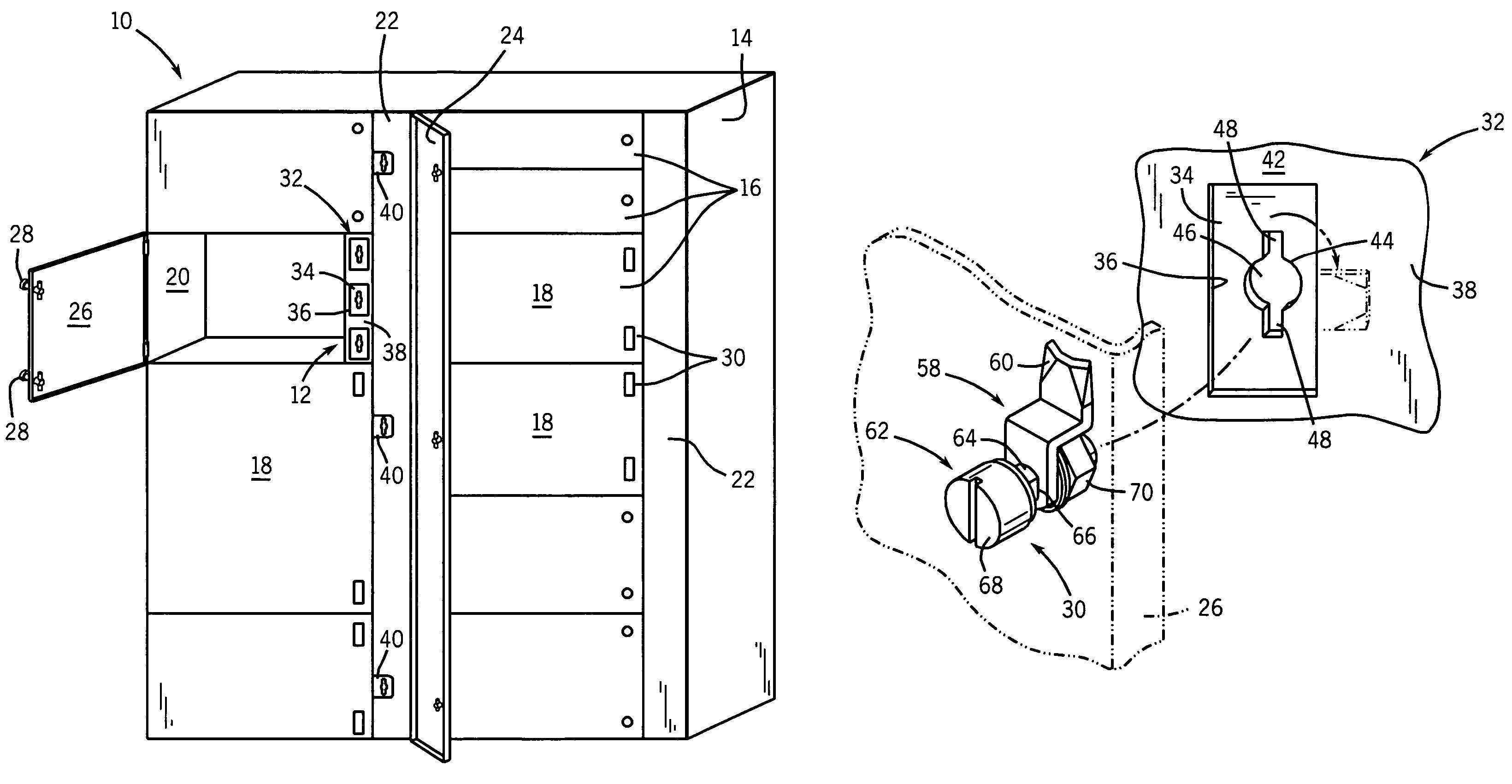
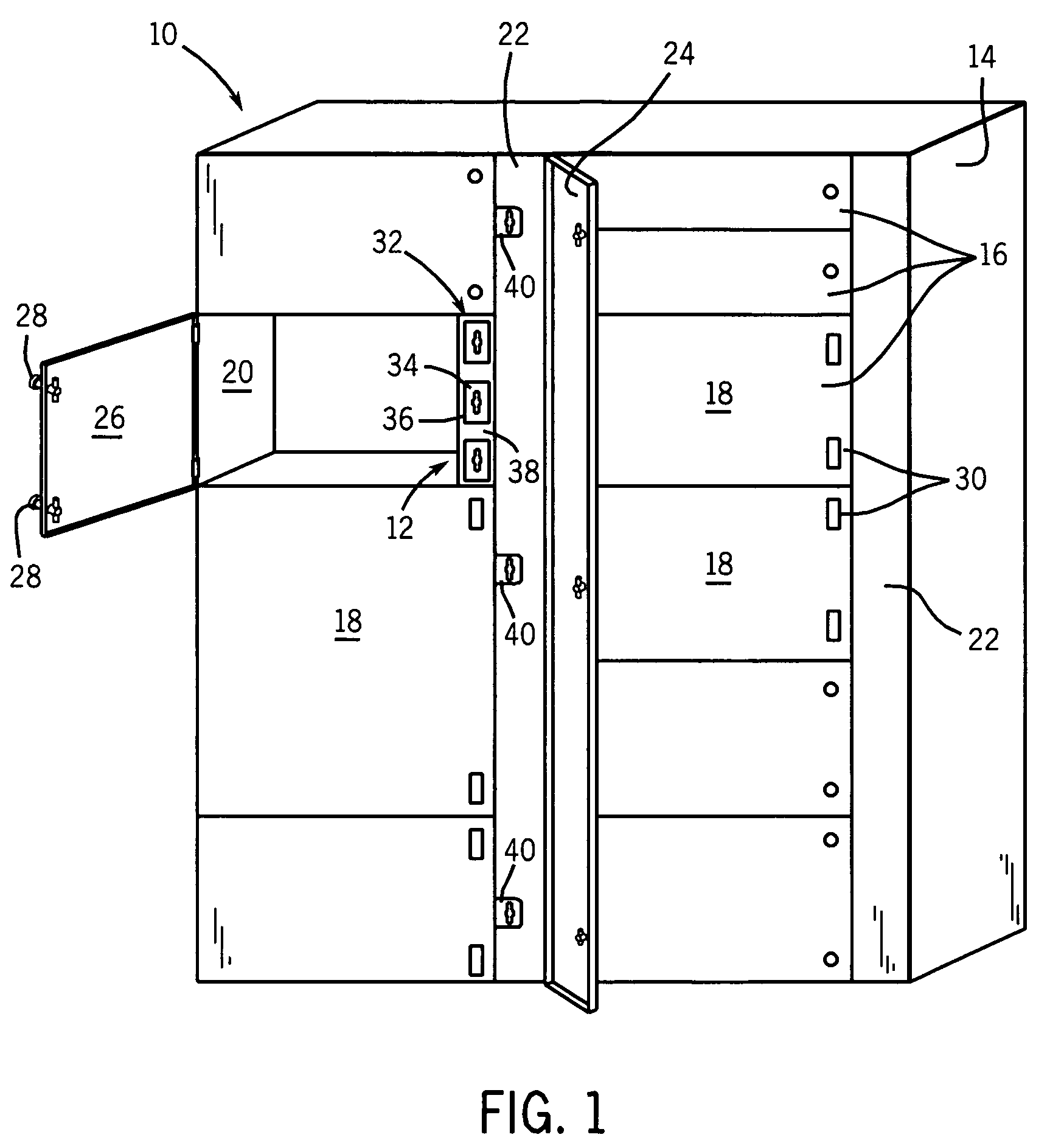
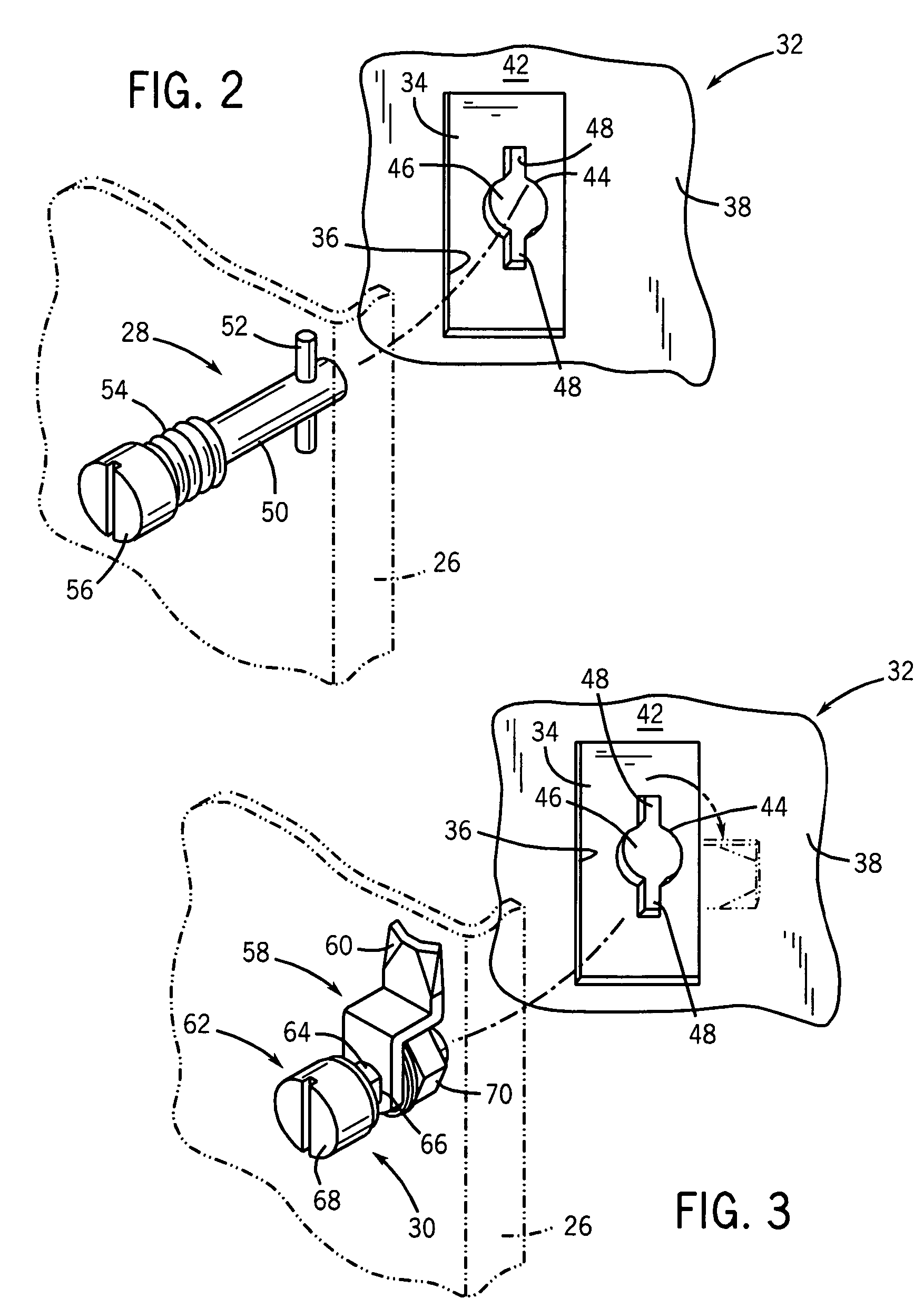
[0018]Turning now to the drawings, and referring first to FIG. 1, an enclosure 10 is illustrated on which a multi-latch compatible system 12 is installed. The enclosure may be any suitable type and size. In the illustrated embodiment, for example, the enclosure may house an industrial motor control center. The enclosure generally includes a shell 14 which, in the illustrated embodiment, is divided into compartments 16, each having a corresponding door 18. The doors 18 may be opened and closed to gain access to an interior volume 20.

[0019]It should be noted that the present techniques are in no way limited, however, to any particular enclosure type or style. The invention will find application with enclosures made of conventional sheet metal, but may also be used with fiberglass enclosures, plastic enclosures, and so forth. The multi-latch compatible system described below may also be suitable for enclosures with a single door or with multiple doors and compartments. Similarly, the s...


PUM


Abstract

A multi-latch compatible system is disclosed for electrical enclosures. The system accommodates latches of different types and configurations. A rail structure may be formed to interface with pin-type latches and with plate-type latches. The rail structure may be configured as a pre-assembled insert that can be placed within an electrical enclosure. The system permits the same general structure to be used regardless of the type of latching mechanism selected and installed in the enclosure.

Description

BACKGROUND[0001]The present invention relates generally to the field of electrical enclosures. More particularly the invention relates to mechanisms for latching electrical enclosures in a closed position to house power electronic and other electrical circuit components within a controlled volume.[0002]A wide range of applications exist for electrical enclosures of all types. Such enclosures are used heavily in industry, but also in mobile applications, offshore applications, consumer and commercial applications, and so forth. In general, electrical enclosures typically include a shell or box made of a heavy gage sheet metal. The enclosures are configured to support electrical circuitry and electrical components therein, and to receive and send electrical power and data signals. The internal components of the enclosure are accessible through doors, hatches and other openings. An important feature in such enclosures is that the doors can be readily opened, but closed and latched secu...

Claims


Application Information

Patent Timeline
Patent Type & Authority Patents(United States)
IPC IPC(8): E05C7/06
CPCE05B65/02H02B1/38E05C3/042
Inventor BERGMANN, HERBERTOFURTADO, JOSE FERNANDOMALKOWSKI, JR., CHESTEROMOTO, ARNALDO HIROYUKINETO, JOSE BATISTA FERREIRA
Owner ROCKWELL AUTOMATION TECH
Learn More