Radial and thrust snap bearing retainer

a technology of snap bearings and retainers, which is applied in the direction of connection, electrical apparatus, coupling device connection, etc., can solve the problems of snap bearing wear and degradation, conventional snap bearing deformation, etc., and achieve the effect of reducing the bearing pressure on the components

Inactive Publication Date: 2010-06-01
PPC BROADBAND INC
View PDF6 Cites 2 Cited by
  • Summary
  • Abstract
  • Description
  • Claims
  • Application Information

AI Technical Summary

Benefits of technology

[0010]An advantage of the present invention is that the concave surface allows the center span of the snap bearing to flex during assembly of the components of the connector without exceeding the elastic limit of the bearing. The concave surface thus allows for a large bearing surface, thus reducing the bearing pressures on the components.
is that the concave surface allows the center span of the snap bearing to flex during assembly of the components of the connector without exceeding the elastic limit of the bearing. The concave surface thus allows for a large bearing surface, thus reducing the bearing pressures on the components.

Problems solved by technology

The minimal overlap results in high bearing pressures and high friction forces in the interface between the components resulting in wear and degradation of the snap ridge.
However, radial loads, such as those applied during assembly, may cause deformation of conventional snap bearings.

Method used


Image

  • Radial and thrust snap bearing retainer
  • Radial and thrust snap bearing retainer
  • Radial and thrust snap bearing retainer

Examples


Embodiment Construction

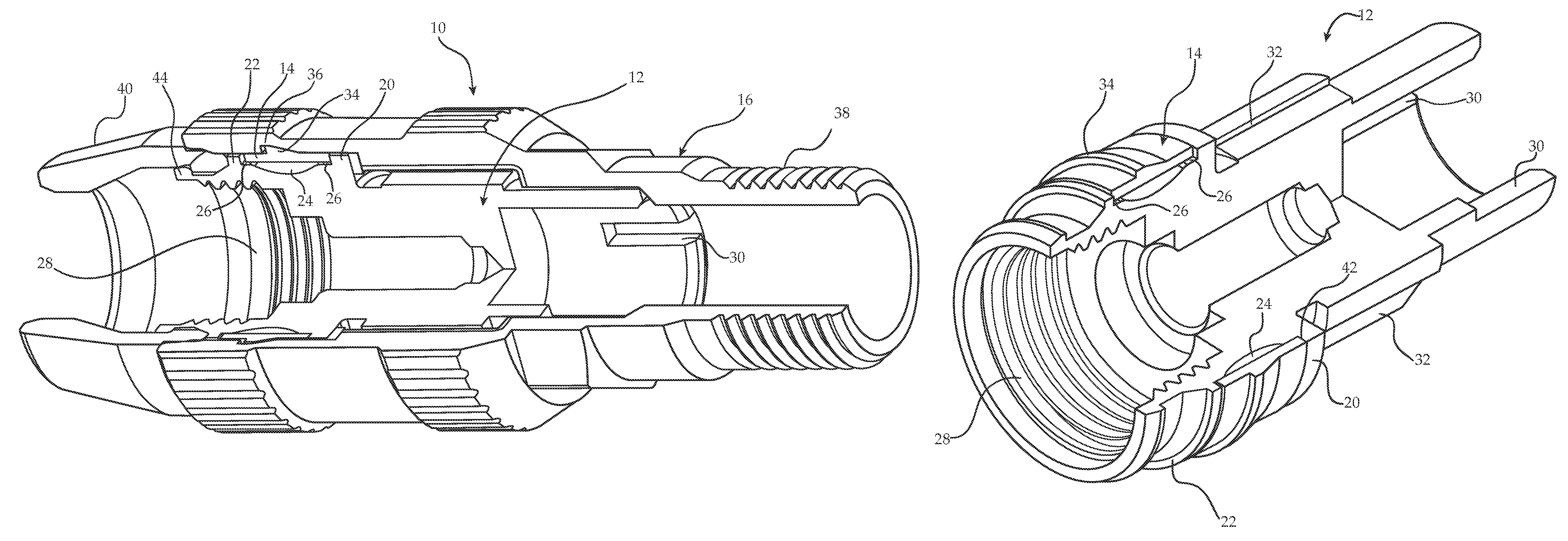
[0018]FIG. 1 shows the coaxial connector of the present invention. By way of example, the connector described is a tamper-resistant terminator connector, though the invention may also be applied to other coax connectors having an outer part that rotates relative to an inner part. The connector 10 includes an inner body 12, a snap bearing 14, and an outer body 16.

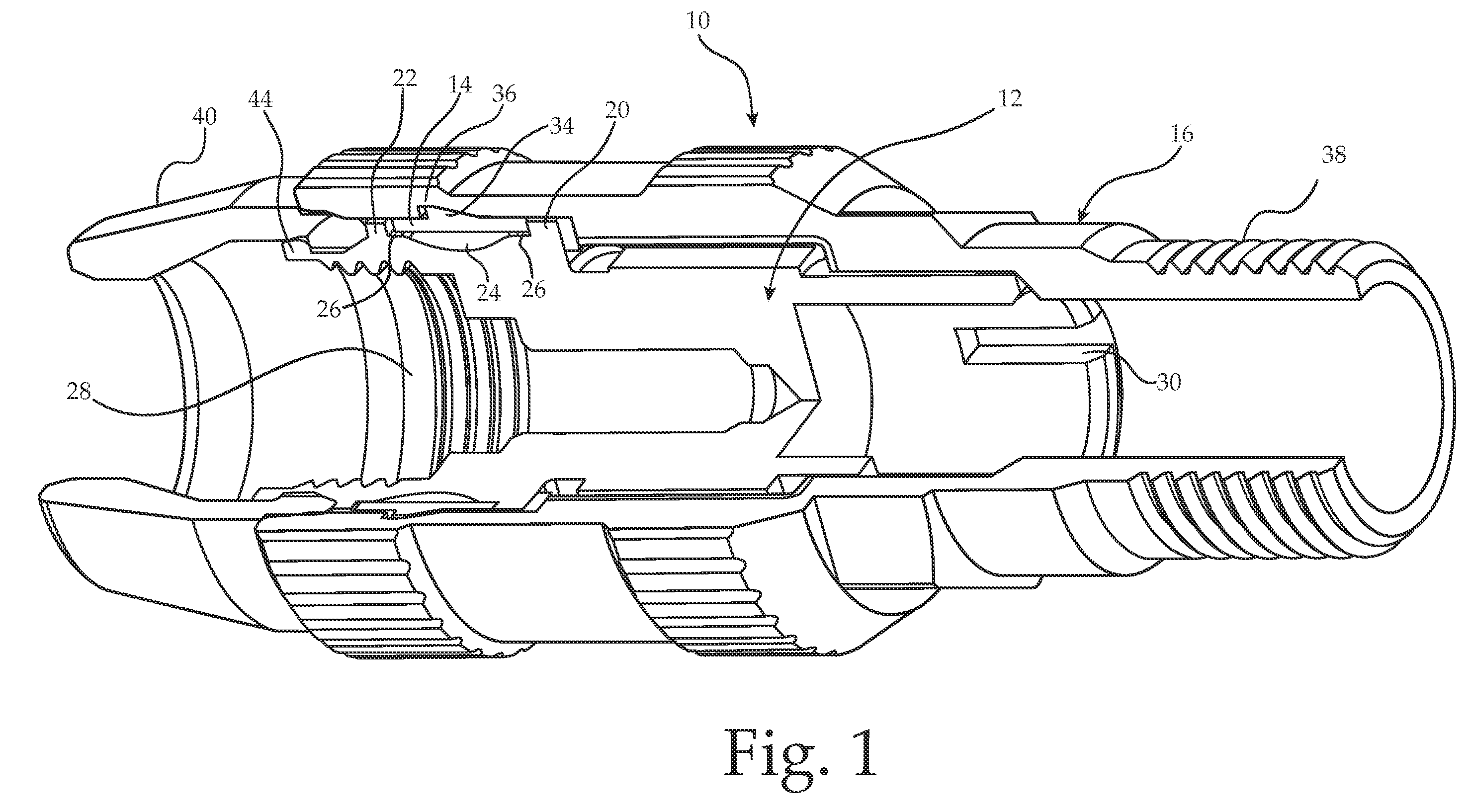
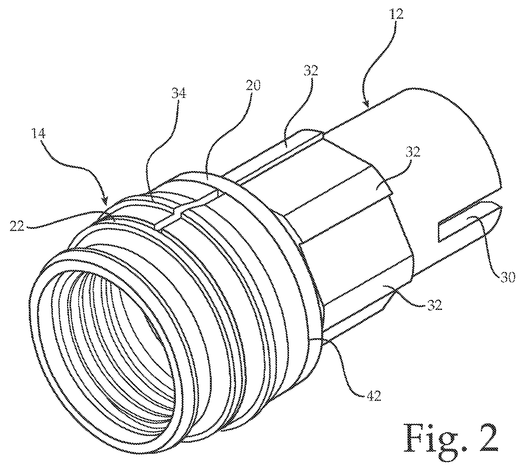
[0019]The inner body 12, as shown in FIGS. 2 and 3, includes a retaining shoulder 20, a snap shoulder 22, and a concave surface 24. The concave surface 24 includes an edge 26 proximate to each of the retaining shoulder 20 and the snap shoulder 22. In a particular embodiment, the edges 26 are narrow with respect to the concave surface 24 as illustrated in the figures. The inner body 12 further includes inner threads 28 configured for engaging a coaxial port (not shown) and slots 30 configured for engaging a specialized tool 31 (FIG. 5) for threading the threads 28 onto the coaxial port after the terminator connector 10 has be...


PUM


Abstract

The invention provides a connector for coax cable with a snap bearing providing the interface between the inner body and the outer body. A concave surface below the snap bearing, which is retained by a pair of shoulders, allows the snap bearing to elastically deform during assembly of the connector to thereby reduce the risk of plastic deformation of the components while allowing significant improvements in overlap at the interface of the components.

Description

FIELD OF THE INVENTION[0001]This invention relates to connector bodies for coaxial cables.BACKGROUND OF THE INVENTION[0002]For small assemblies, such as coaxial connectors, it is often desirable to use components that are configured to snap together rather than use fasteners. In certain connectors, two parts that are to rotate relative to one another are snapped together with a snap ridge of one part engaging a groove in the other part. The overlap between the components in such connections is typically kept to a minimum, such as a few thousandths of an inch of overlap in brass components, in order to minimize plastic deformation of the components during assembly. The minimal overlap results in high bearing pressures and high friction forces in the interface between the components resulting in wear and degradation of the snap ridge. A terminator connector having a snap fit between an outer body and an inner body is described in U.S. Pat. No. 6,491,546, issued to Jason Perry, the dis...

Claims


Application Information

Patent Timeline
Patent Type & Authority Patents(United States)
IPC IPC(8): H01R9/05
CPCH01R13/6397H01R9/0521
Inventor MONTENA, NOAHCHAWGO, SHAWN
Owner PPC BROADBAND INC
Why Eureka
Try Eureka