Multi-helical ball sleeve structure

a multi-helical ball and sleeve technology, applied in the direction of bearings, shafts and bearings, bearings, etc., can solve the problems of increasing the pressure bearing point of the conventional ball sleeve, increasing the bearing pressure of the conventional ball sleeve, increasing the coefficient, etc., to increase the pressure bearing point of the ball sleeve, increase the working efficiency, and increase the life

Inactive Publication Date: 2005-02-08
CHU EN TE
View PDF2 Cites 2 Cited by
  • Summary
  • Abstract
  • Description
  • Claims
  • Application Information

AI Technical Summary

Benefits of technology

The primary objective of the present invention is to provide a multi-helical ball sleeve structure that can enhance the lifetime and increase the working efficiency.
Another objective of the present invention is to provide a multi-helical ball sleeve structure, wherein the pressure bearing points of the ball sleeve are increased, thereby reducing the bearing pressure of each point of the ball sleeve.
A further objective of the present invention is to provide a multi-helical ball sleeve structure, wherein the bearing pressure of each point of the ball sleeve is reduced, thereby increasing the lifetime of the ball sleeve, and thereby enhancing the working efficiency of the ball sleeve.
A further objective of the present invention is to provide a multi-helical ball sleeve structure, wherein the force contact face of the ball sleeve is enlarged and the force is distributed evenly, so that the ball sleeve is not easily broken or worn out during a long-term utilization, thereby increasing the lifetime of the ball sleeve.
A further objective of the present invention is to provide a multi-helical ball sleeve structure, wherein the ball sleeve needs not to be replaced frequently, thereby increasing the working efficiency.

Problems solved by technology

1. The support points of the conventional ball sleeve 1 are not enough, thereby increasing the bearing pressure of the conventional ball sleeve 1.
2. The contact surface is not evenly distributed, and the friction action is concentrated on the same position, so that the conventional ball sleeve 1 is easily worn out during a long-term utilization.
3. When the conventional ball sleeve 1 is broken, the friction coefficient is increased during the sliding movement, thereby increasing the resistance.
4. The conventional ball sleeve 1 is easily worn out, so that the conventional ball sleeve 1 needs to be replaced frequently, thereby decreasing the working efficiency.
5. The conventional ball sleeve 1 is rotatably and movably mounted in a guide sleeve 4. The balls 3 receiving in the through holes 2 of the conventional ball sleeve 1 have the same circumferential height, so that the guide sleeve 4 is easily worn out during a long-term utilization, thereby increasing the gap between the upper die (not shown) and the lower die (not shown) of the mold (not shown), and thereby wearing the mold.

Method used


Image

  • Multi-helical ball sleeve structure
  • Multi-helical ball sleeve structure
  • Multi-helical ball sleeve structure

Examples


Embodiment Construction

Referring to the drawings and initially to FIGS. 4-6, a multi-helical ball sleeve structure in accordance with a preferred embodiment of the present invention comprises a cylindrical ball sleeve 10 formed with a plurality of through holes 11, and a plurality of balls 20 each received in a respective one of the through holes 11. The through holes 11 are fully and completely distributed around a whole circumference of the ball sleeve 10. The through holes 11 are arranged in an oblique manner. The through holes 11 are arranged in a helical manner. In addition, the distance between the through holes 11 is relatively smaller. Thus, the bearing pressure of the ball sleeve 10 is reduced, and the lifetime of the ball sleeve 10 is increased.

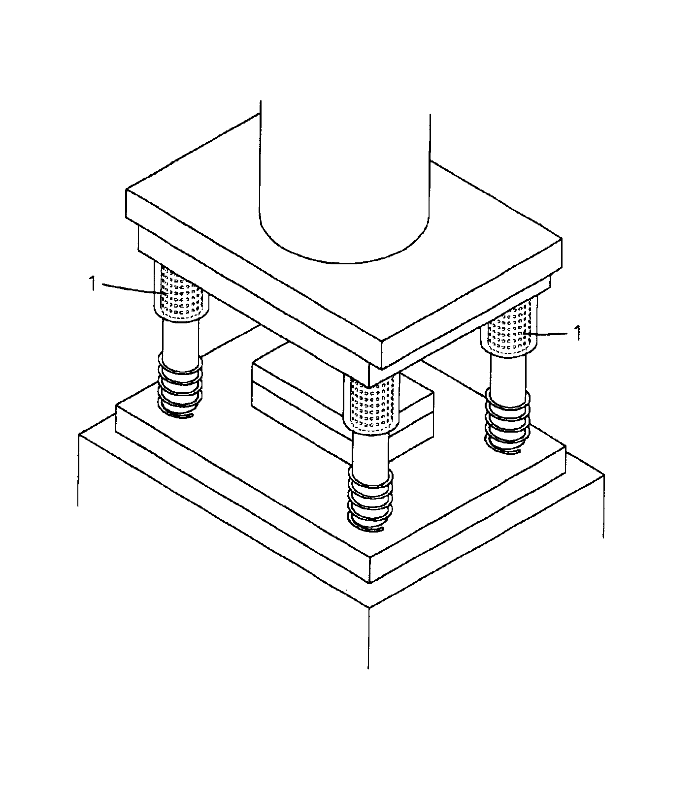
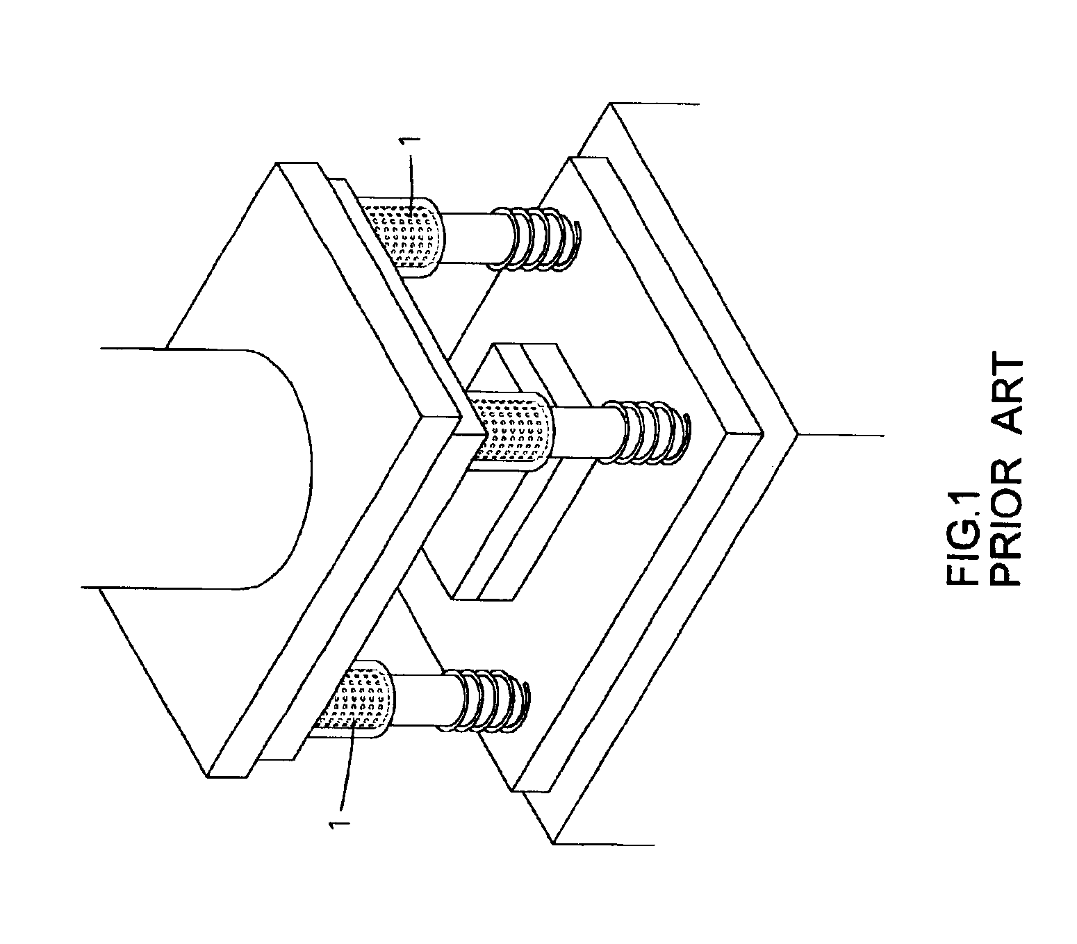
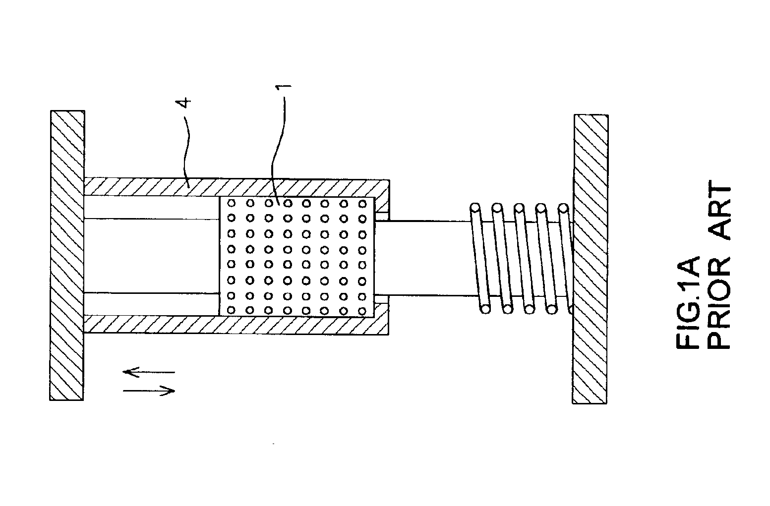
In comparison, as shown in FIG. 7, the ball sleeve 10 in accordance with the present invention is compared with the conventional ball sleeve 1 in accordance with the prior art.

In the conventional ball sleeve 1, the distance between the through a holes 2 i...


PUM


Abstract

A multi-helical ball sleeve structure includes a cylindrical ball sleeve formed with a plurality of through holes, and a plurality of balls each received in a respective one of the through holes. The through holes are arranged in an oblique and helical manner. Thus, the multi-helical ball sleeve structure can enhance the lifetime and increase the working efficiency.

Description

BACKGROUND OF THE INVENTION1. Field of the InventionThe present invention relates to a multi-helical ball sleeve structure, and more particularly to a multi-helical ball sleeve structure that can enhance the lifetime and increase the working efficiency.2. Description of the Related ArtA working machine, such as a punching bed, is used for processing a workpiece. In general, the punching bed is provided with a plurality of ball sleeves to reduce the friction. A conventional ball sleeve 1 in accordance with the prior art shown in FIGS. 1-3 is mounted on the punching bed to reduce the friction of the punching bed during the working process. The conventional ball sleeve 1 is formed with a plurality of through holes 2 for receiving a plurality of balls 3.However, the conventional ball sleeve 1 has the following disadvantages.1. The support points of the conventional ball sleeve 1 are not enough, thereby increasing the bearing pressure of the conventional ball sleeve 1.2. The contact surf...

Claims


Application Information

Patent Timeline
Patent Type & Authority Patents(United States)
IPC IPC(8): F16C29/04
CPCF16C33/40F16C29/04
Inventor CHU, EN TE
Owner CHU EN TE
Why Eureka
Try Eureka