Welding spot protecting structure of condensation heat exchanger

A technology for condensing heat exchangers and protective structures, which is applied in the direction of damage protection, heat exchange equipment, lighting and heating equipment, etc., and can solve the problems of difficulty in meeting the anti-corrosion requirements of condensing heat exchangers, large internal and external pressure differences of solder joints, and strong solder joints. Corrosion and other issues, to achieve the effect of ensuring reliability, long service life, and strong corrosion resistance

Active Publication Date: 2014-10-29
MACRO THERMAL ENERGY TECH
View PDF5 Cites 2 Cited by
  • Summary
  • Abstract
  • Description
  • Claims
  • Application Information

AI Technical Summary

Problems solved by technology

[0003] Since the condensing heat exchanger works in a high-temperature and high-humidity environment, the solder joints are in contact with water, high-temperature flue gas, condensed water and other substances for a long time, especially the condensed water is weakly acidic, which has strong corrosion on the contacted solder joints In many cases, ordinary brazing is difficult to meet the anti-corrosion requirements of condensing heat exchangers
In addition, due to the high water pressure in the heat exchange pipe, the pressure in the heat exchange chamber is about 50 Pa, and the pressure difference between the inside and outside of the solder joint is large. Once corrosion occurs, water leakage will easily occur.

Method used


Image

  • Welding spot protecting structure of condensation heat exchanger

Examples


Embodiment Construction

[0022] In order to facilitate those of ordinary skill in the art to better understand the essence of the present invention, the specific implementation manners of the present invention will be described in detail below in conjunction with the accompanying drawings.

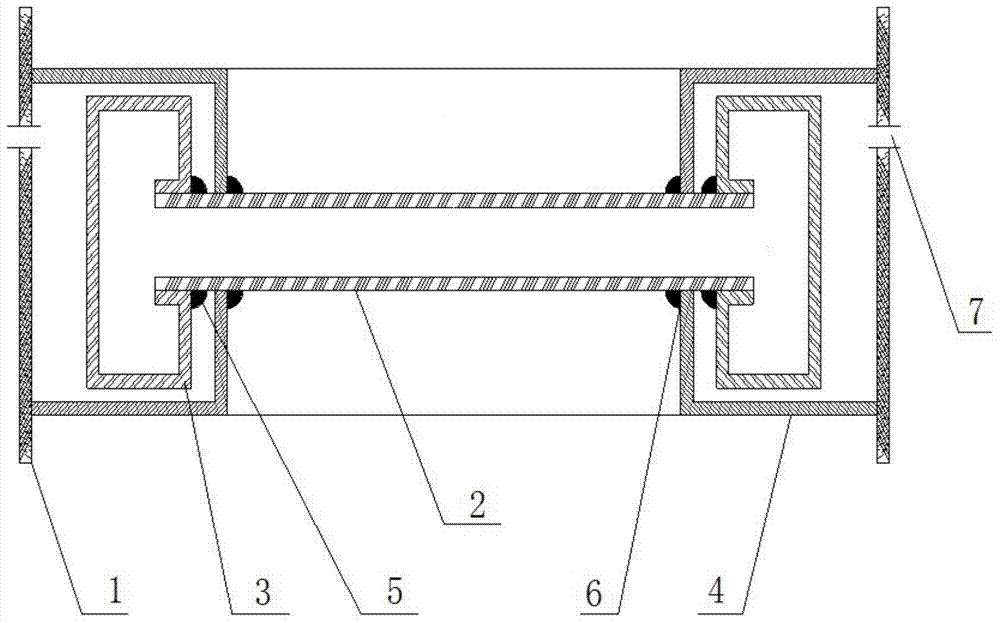
[0023] like figure 1 As shown, a solder joint protection structure of a condensation heat exchanger is characterized in that a smoke isolation chamber is provided around the solder joint 5 of the stainless steel heat exchange tube 2, and the smoke isolation chamber completely surrounds the solder joint and the smoke The shell of the gas isolation chamber is not in contact with the solder joint 5 .

[0024] In this embodiment, preferably, the flue gas isolation cavity is surrounded by the isolation baffle 4 and the condensation heat exchanger shell 1, and the isolation baffle 4 and the stainless steel heat exchange tube 2 are fixed by welding. In this way, during actual work, the high-temperature and high-humidity...


PUM


Abstract

The invention discloses a welding spot protecting structure of a condensation heat exchanger. The welding spot protecting structure is characterized in that a gas fume isolating cavity is formed around a welding spot of a heat exchange water pipe and completely encircles the welding spot, and a shell of the gas fume isolating cavity does not make contact with the welding spot. The gas fume isolating cavity is formed by an isolating baffle and a shell of the condensation heat exchanger in a defined mode, and the isolating baffle and the heat exchange water pipe are fixed through welding. In this way, high-temperature high-humidity gas fume in the condensation heat exchanger does not make direct contact with the welding spot and only makes contact with the welding seam between the isolating baffle and the stainless steel heat exchange pipe in the actual working process, as the welding seam does not bear pressure, the corrosion resistance of the welding seam is good, the welding spot is effectively prevented from being corroded, and the service life of the welding spot is prolonged.

Description

technical field [0001] The invention relates to the technical field of components for fluid heaters, in particular to a protection structure for solder joints of condensing heat exchangers. Background technique [0002] During the preparation process of the condensing heat exchanger, the heat exchange pipe and the water storage tank are usually sealed by welding. At present, the common welding processes mainly include argon arc welding and brazing. The argon arc welding connection is reliable, but due to the limitation of the welding process, there are high requirements for the thickness and strength of the welding material, and the design form of its structure is also subject to many restrictions. Brazing is convenient for welding and flexible in application, but the corrosion resistance has a lot to do with the corrosion resistance of the solder. [0003] Since the condensing heat exchanger works in a high-temperature and high-humidity environment, the solder joints are ...

Claims


Application Information

Patent Timeline
Patent Type & Authority Applications(China)
IPC IPC(8): F28F19/00
Inventor 余少言史玉军王克军胡旭李江
Owner MACRO THERMAL ENERGY TECH
Why Eureka
Try Eureka