
Color image compressing method and device

a compression method and color image technology, applied in image data processing, digitally marking record carriers, instruments, etc., can solve the problems of large brightness and color changes, difficult to improve data compression ratio, and inability to conduct clear area determination, so as to reduce the number of clusters needed to determine their respective characteristics and improve the compression ratio

Inactive Publication Date: 2010-06-01
FUJITSU LTD +1
View PDF17 Cites 11 Cited by
  • Summary
  • Abstract
  • Description
  • Claims
  • Application Information

AI Technical Summary

Benefits of technology

This approach improves the compression ratio while maintaining clear outlines of characters and ruled lines, allowing for more efficient data storage and accurate area determination in compressed images.

Problems solved by technology

However, since image information is compressed by coarsely quantizing its RF element, the edge of a character that has a large change in brightness and color and the like becomes unclear, which is a problem.
Therefore, no clear area determination can be conducted, which is another problem.
However, since in the method of Patent reference 1, data indicating the location of a black edge must be transmitted separately from color image data, it is difficult to improve a data compression ratio.
All the above-mentioned conventional compression methods realize compression by reducing the redundancy of image data after being read by a scanner and the like, and can not reduce redundancy caused when the scanner and the like reads a manuscript, by extracting the features of the ruled lines, characters or the like of the original manuscript.
Therefore, a color image including a ruled line, a character and the like cannot be compressed at a high compression ratio and also the outline of a character and the like cannot be clearly displayed.

Method used


Image

  • Color image compressing method and device
  • Color image compressing method and device
  • Color image compressing method and device

Examples


Embodiment Construction

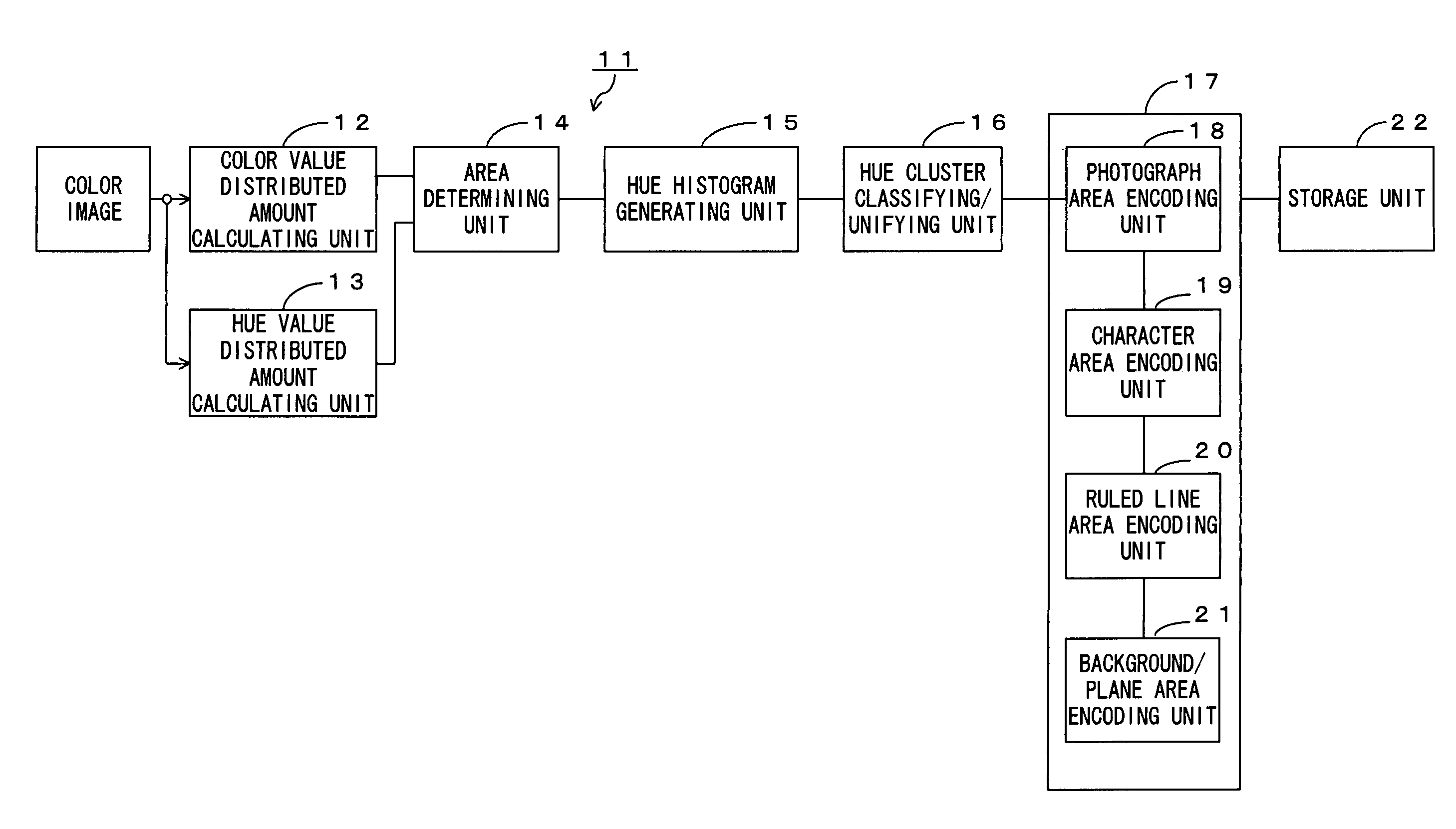
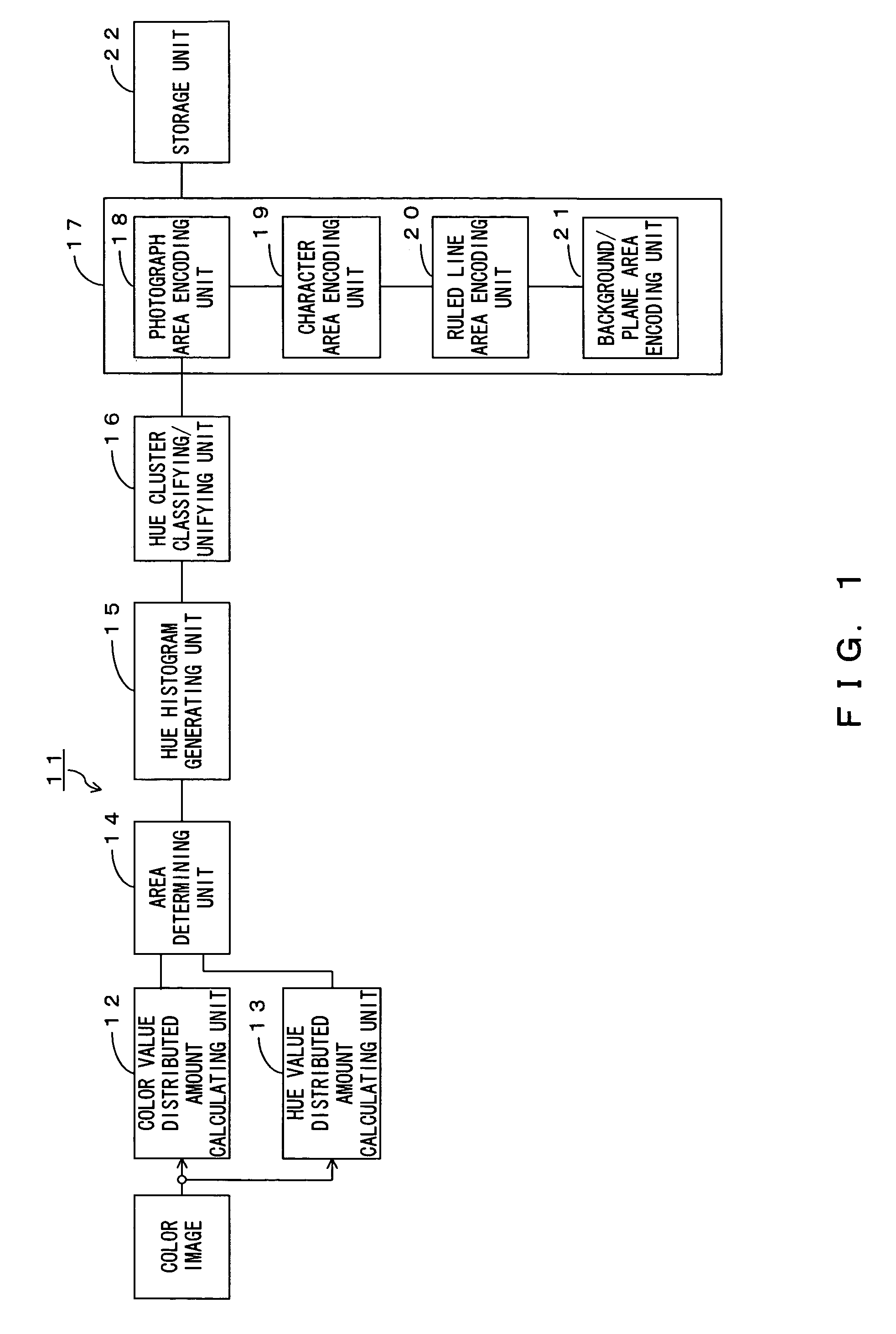
[0049]The preferred embodiments of the present invention are described below with reference to the drawings. FIG. 1 shows the configuration of a color image compressing device according to the present invention.

[0050]In the following description, it is assumed that a four-to-six color printed manuscript is read by an optical sensor, such as a scanner or the like, and the read color image is compressed. It can also be a color image photographed or read by a camera or the like.

[0051]If a scanner reads a four-to-six color printed image, a far greater number of R, G and B color data than that of an original manuscript is generated from a read color image since the shade of ink and the respective positions of R, G and B optical sensors are not uniform. Usually several tens of thousands of color images are outputted from a scanner.

[0052]In FIG. 1, a hue value distributed amount calculating unit 12 divides an inputted color image into a predetermined number of areas, and calculates the res...


PUM


Abstract

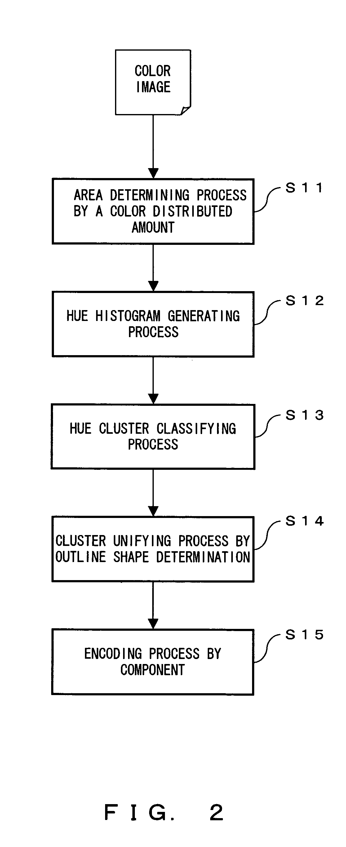
It is an object of the present invention to improve the compression ratio of a color image and to clearly display the outlines of characters and the like. A hue cluster classifying / unifying unit reduces the number of hue values of each pixel in a color image, based on a hue histogram, allocates the number-reduced hue value to each pixel and classifies pixels with the same hue value into one cluster. Furthermore, the unit unifies clusters whose hue values are below a predetermined value. The unit also traces the outline of a cluster whose size is below a reference value and determines that a cluster that has a lot of change points belongs to a character area. An encoding unit determines the characteristic of each cluster, based on both an area determined by an area determining unit and whether the cluster belongs to a ruled line area or a character area, and encodes pixels in each cluster by a coding method suitable for the characteristic of the cluster.

Description

BACKGROUND OF THE INVENTION[0001]1. Field of the Invention[0002]The present invention relates to a color image compressing method for compressing color images read by a scanner or the like and a device thereof.[0003]2. Description of the Related Art[0004]JPEG (joint photographic coding experts group) coding is conventionally known as an image compressing method. JPEG coding divides an image into a plurality of blocks, performs discrete cosine transform (DCT) and quantizes / encodes the obtained values.[0005]JPEG coding is suitable for compressing images, such as a photograph and the like. However, since image information is compressed by coarsely quantizing its RF element, the edge of a character that has a large change in brightness and color and the like becomes unclear, which is a problem.[0006]In order to solve such a problem, Patent reference 1 discloses a technology for transmitting / receiving images superior in reproducing black edges by extracting the black edge of a color imag...

Claims


Application Information

Patent Timeline
Patent Type & Authority Patents(United States)
IPC IPC(8): H04N1/46G06F15/00G06K1/00H04N1/60G06T9/00G06K9/20G06K9/34G06K9/36G06T7/00H04N1/40H04N1/41H04N1/56H04N1/64H04N19/00
CPCH04N1/642G06K9/00456G06V30/413H04N1/6075
Inventor EGUCHI, SHINICHIKANAMOTO, KOUICHISUZUKI, NAOKOKATSUMATA, YUTAKA
Owner FUJITSU LTD
Learn More