Fuel injection control device

a control device and fuel injection technology, applied in the direction of electrical control, process and machine control, instruments, etc., can solve the problems of failure to inject the desired mass of fuel, output energy differences between cylinders, etc., and achieve the effect of reducing the likelihood of misfir

Inactive Publication Date: 2010-06-01
ISUZU MOTORS LTD
View PDF12 Cites 16 Cited by
  • Summary
  • Abstract
  • Description
  • Claims
  • Application Information

AI Technical Summary

Benefits of technology

[0009]In fuel injection control devices for controlling fuel injection by an injector, multiple injection (multi-injection) control, in which the amount of fuel to be supplied in one combustion cycle is divided into a plurality of fuel injections, is known. In multiple injection control, a fuel injection that carries out 4 fuel injections is known, wherein the injections, called pilot injection, pre-injection, main injection, and after-injection, follow an injection execution sequence; in recent years, post-injection is being carried out after after-injection, for forced regeneration through a raise in exhaust temperature, with the objective of preventing filter clogging.
[0016]Therefore, an object of the present invention is to solve the above problems and to provide a fuel injection control device that prevents misfires.
[0020]The present invention affords the following effect: changes in the number of injections are suppressed in multiple injection, through injection amount correction, thereby reducing the likelihood of misfires.

Problems solved by technology

Specifically, even when an injection amount instructed from a computer to the injector is constant, the injection amount actually injected by the injector shows variations, albeit small variations, among individual injectors, which results in output energy differences among cylinders.
That is, when volume increases due to thermal expansion, a desired mass of fuel fails to be injected even if the injector injects a certain volume of fuel.

Method used


Image

  • Fuel injection control device
  • Fuel injection control device
  • Fuel injection control device

Examples


Embodiment Construction

[0028]An embodiment of the present invention is explained next with reference to accompanying drawings.

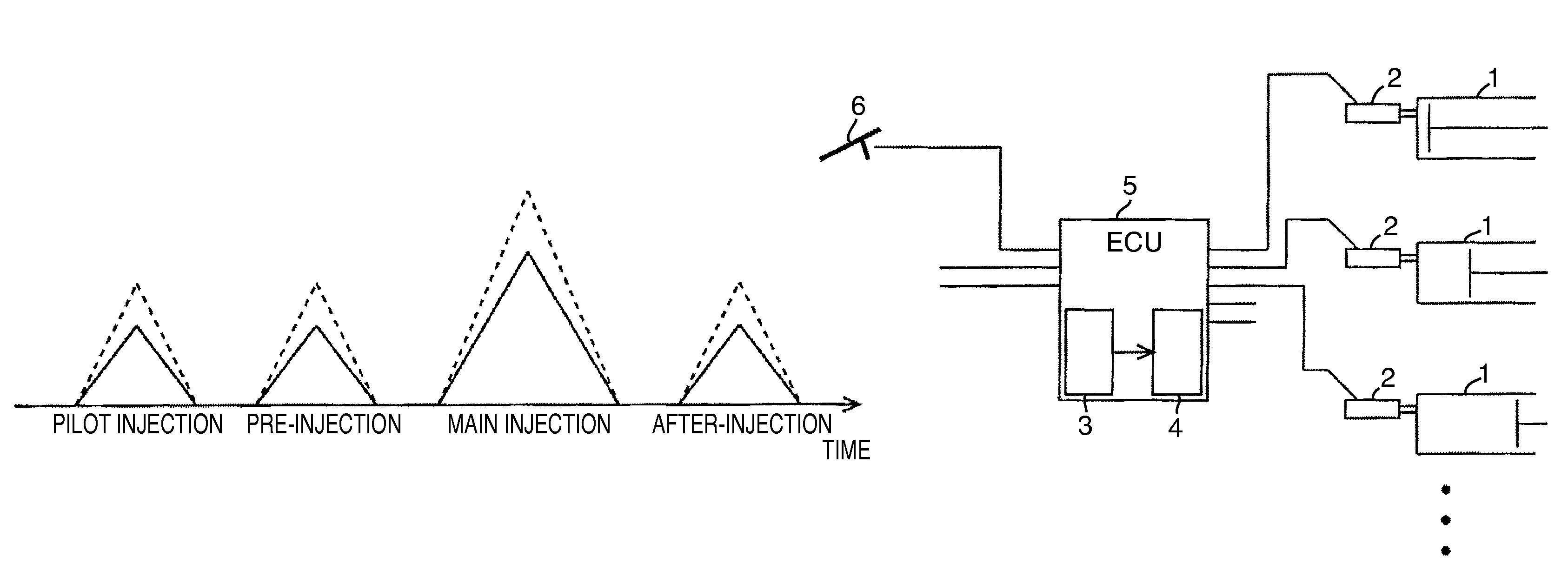
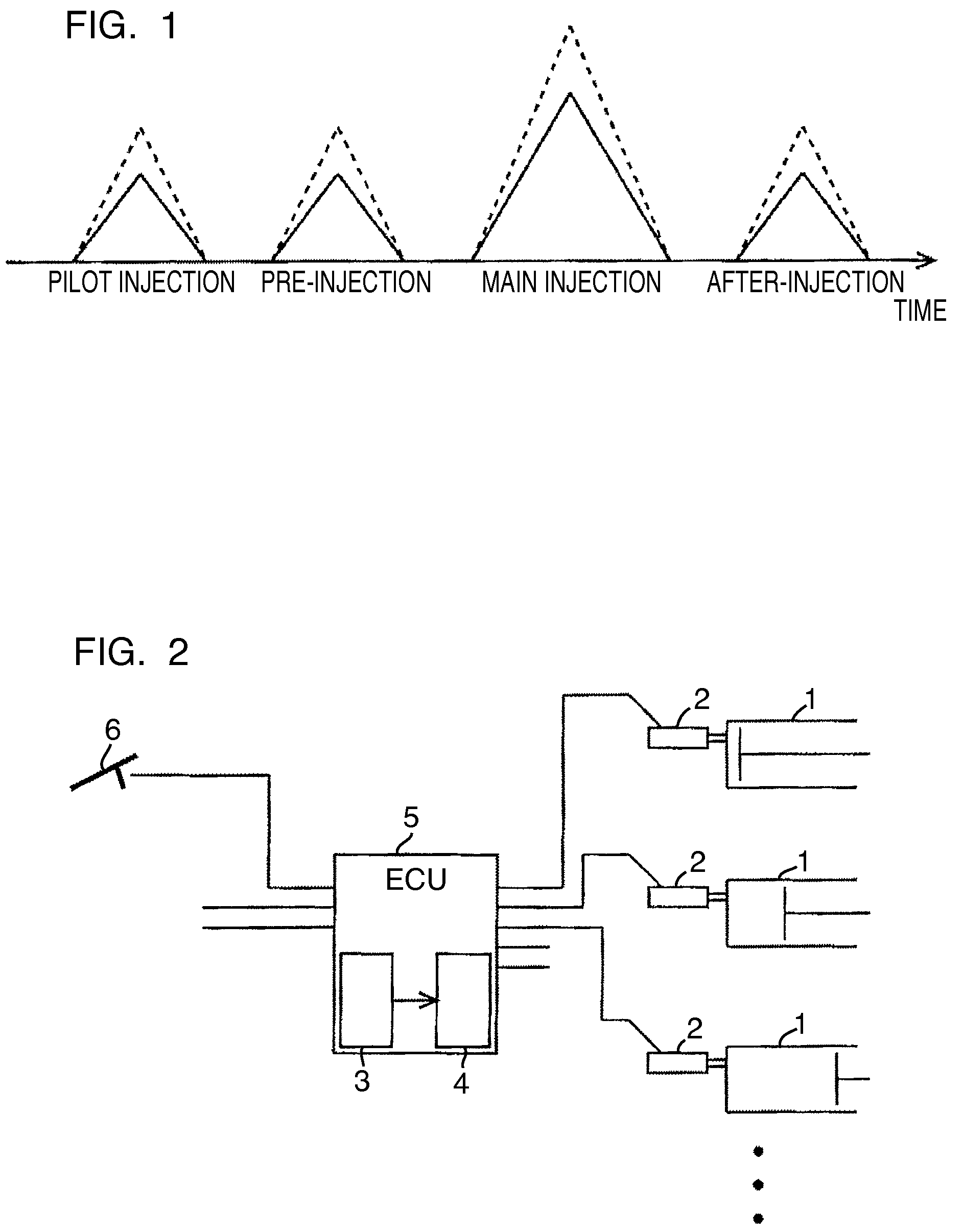
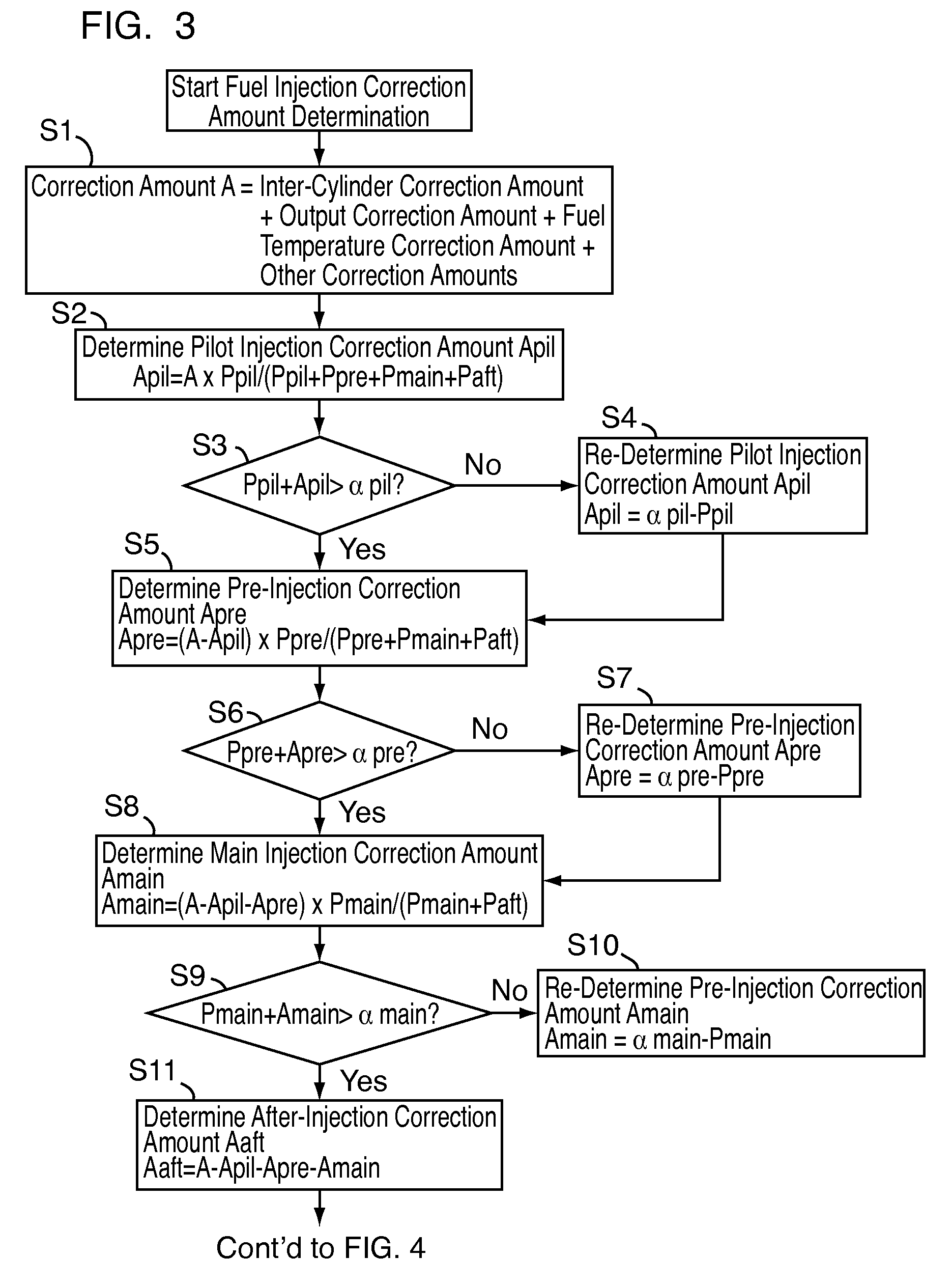
[0029]The basic principle of the present invention will be explained on the basis of an example in which fuel injection is carried out divided into four fuel injections, i.e. pilot injection, pre-injection, main injection, and after-injection, such that the amount of fuel to be injected to a concerned cylinder in one combustion cycle and the correction amount in one combustion cycle are summed:

Ppil+Ppre+Pmain+Paft+A=P′pil+P′pre+P′main+P′aft  (1)

wherein Ppil is a target pilot injection amount, Ppre is a target pre-injection amount, Pmain is a target main injection amount, Paft is a target after-injection amount, A is a correction amount in one combustion cycle, P′pil is a pilot injection amount after correction, P′pre is a pre-injection amount after correction, P′main is a main injection amount after correction, and P′aft is an after-injection amount after correction. The correction...


PUM


Abstract

A fuel injection control device that prevents a misfire is provided. The fuel injection control device comprises: target injection amount determination means 3 for determining a target injection amount of each fuel injection, so that the amount of fuel to be supplied to a cylinder in one combustion cycle is supplied in a plurality of fuel injections; and fuel injection correction amount determination means 4 for determining a fuel correction amount of one combustion cycle, wherein the fuel injection correction amount determination means 4 distributes the correction amount among each fuel injection in accordance with the ratio of a target injection amount of each fuel injection in the cylinder.

Description

CROSS REFERENCE TO RELATED APPLICATIONS[0001]This application is entitled to the benefit of and incorporates by reference essential subject matter disclosed in International Patent Application No. PCT / JP2006 / 312511 filed on Jun. 22, 2006 and Japanese Patent Application No. 2005-206757 filed on Jul. 15, 2005.TECHNICAL FIELD[0002]The present invention relates to a fuel injection control device for carrying out multiple injection in a plurality of cylinders, and to a fuel injection control device for preventing misfire.BACKGROUND ART[0003]When fuel injection is carried out by an injector, a computer (ECU) determines the amount of fuel to be supplied in one combustion cycle on the basis of factors such as amount of an accelerator pedal stroke, engine speed and the like.[0004]In the case of an engine having a plurality of cylinders, an injector is arranged in each cylinder, so that a respective injector injects fuel into the corresponding cylinder. Therefore, individual variability in th...

Claims


Application Information

Patent Timeline
Patent Type & Authority Patents(United States)
IPC IPC(8): G06F19/00F02M51/00F02D41/34F02D41/38
CPCF02D41/403F02D41/405F02D41/1498Y02T10/44F02D2200/1015Y02T10/40
Inventor IWASHITA, TAKUROHASEYAMA, TAKASHIWATANABE, YOSHINOBUOCHI, NAOFUMIHAGIO, KENJIMASHIKO, TATSUO
Owner ISUZU MOTORS LTD
Why Eureka
Try Eureka