Eureka AIR delivers breakthrough ideas for toughest innovation challenges, trusted by R&D personnel around the world.

Separator

a separation device and filter technology, applied in the field of separation devices, can solve the problems of low separation efficiency, contamination risk, cellular damage, etc., and achieve the effects of suppressing cell adhesion, suppressing filter blockage, and high adhesion

Inactive Publication Date: 2013-10-10
SEIKO EPSON CORP +1
View PDF18 Cites 4 Cited by
  • Summary
  • Abstract
  • Description
  • Claims
  • Application Information

AI Technical Summary

Benefits of technology

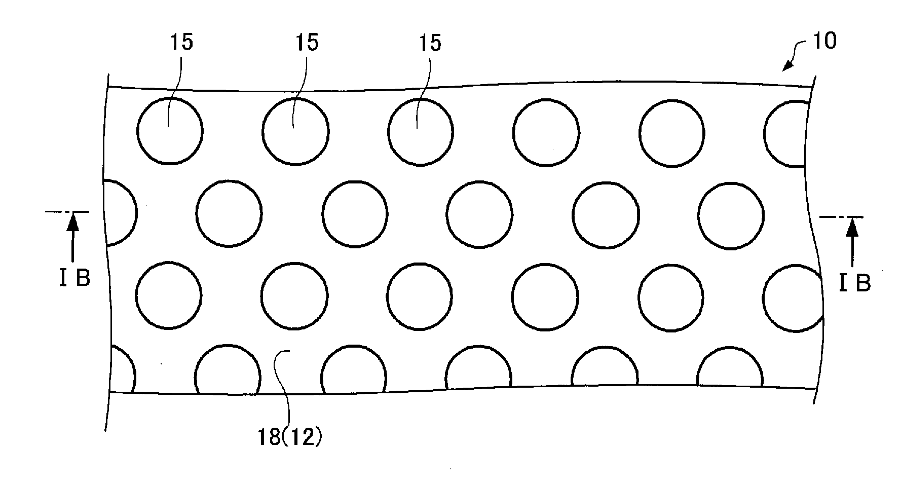
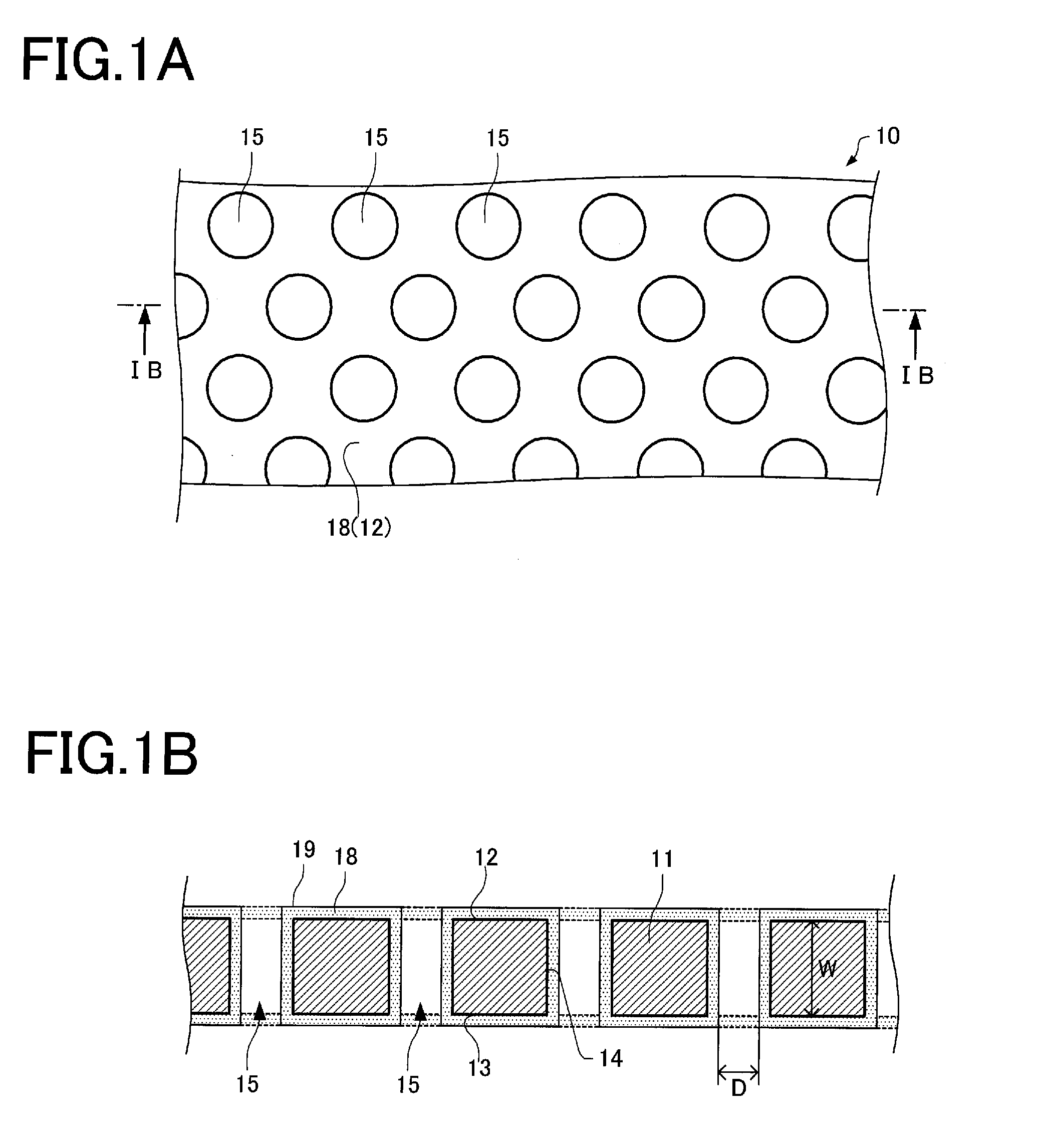
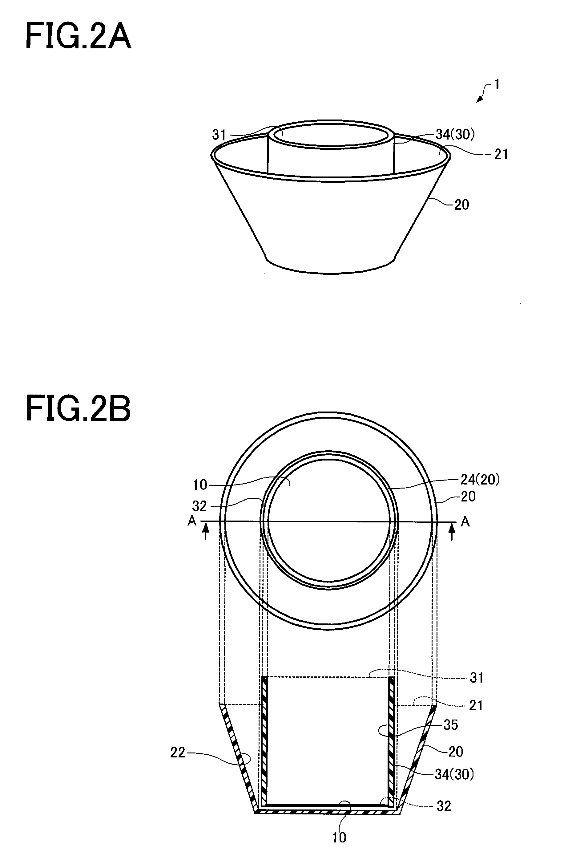
The invention provides a separator that prevents clogging of filters and improves the efficiency of separation.

Problems solved by technology

However, peripheral blood collected from the patient contains a large amount of lymphocytes and the like in addition to monocytes.
However, these methods pose various problems (e.g., contamination risk, cellular damage, low separation efficiency, long-time treatment process, and high reagent cost).
Accordingly, when separating cells having phagocytic activity from peripheral blood or the like using a filter, cells having phagocytic activity easily adhere to the surface of the filter, and clog the filter as compared with other blood cells.

Method used


Image

  • Separator
  • Separator
  • Separator

Examples


example 1

[0088]Au was deposited on the surface of an Si substrate to form an Au film (thickness: 300 nm). A self-assembled monolayer (SAM) was formed on the Au film (SAM treatment). More specifically, the surface of the substrate was UV-cleaned (nm, W×5 min), and the substrate was immersed for 4 hours in a solution prepared by dissolving (diluting) an alkanethiol compound having a polyethylene glycol chain (PEG thiol) in (with) ethanol (0.1%). The substrate was washed with ethanol, and then washed with purified water. The PEG chain length of the PEG thiol compound was 3 (SAM treatment condition 1). The surface of the substrate obtained by the PEG thiol treatment had a contact angle with water of about 39° (i.e., hydrophilic). Note that the contact angle with water was determined by measuring the contact angle of the substrate with purified water using a contact angle meter (“CA-W” manufactured by Kyowa Interface Science Co., Ltd.).

[0089]10 ml of peripheral blood was 2-fold diluted with a pho...

example 2

[0092]In Example 2, the PEG chain length of the PEG thiol compound was changed to 5 (SAM treatment condition 2). The surface of the substrate obtained by the PEG thiol treatment had a contact angle with water of about 37° (i.e., hydrophilic). The substrate was prepared in the same manner as in Example 1, except that the PEG chain length and the contact angle of the surface were changed as described above.

example 3

[0093]In Example 3, the PEG chain length of the PEG thiol compound was changed to 6 (SAM treatment condition 3). The surface of the substrate obtained by the PEG thiol treatment had a contact angle with water of about 36° (i.e., hydrophilic). The substrate was prepared in the same manner as in Example 1, except that the PEG chain length and the contact angle of the surface were changed as described above.


PUM

PropertyMeasurementUnit
contact angleaaaaaaaaaa
thicknessaaaaaaaaaa
thicknessaaaaaaaaaa

Abstract

A separator fractionates a dispersion of cells including cells having phagocytic activity corresponding to a size of the cells to obtain a dispersion in which the content of the cells having phagocytic activity is higher than that of the dispersion, and includes a filter, at least part of the filter having a hydrophilic surface as a result of being covered with at least one of a self-assembled monolayer that includes an alkanethiol having a nonionic hydrophilic group that is formed on a gold thin film via a sulfur-gold bond, and a homopolymer or a copolymer of an ester of (meth)acrylic acid and at least some of hydrophilic groups of phospholipids that form a biomembrane. The separator is thus configured so that clogging of the filter is suppressed, and the separation efficiency is improved.

Description

[0001]Japanese Patent Application No. 2012-86515 filed on Apr. 5, 2012, is hereby incorporated by reference in its entirety.BACKGROUND OF THE INVENTION[0002]The present invention relates to a separator.[0003]It has been known that cells having phagocytic activity (e.g., monocytes, dendritic cells, and macrophages) are useful for the treatment of various diseases. For example, dendritic cell therapy collects peripheral blood from the patient, removes only monocytes from the collected peripheral blood, subjects the monocytes to in vitro differentiation into dendritic cells, allows the dendritic cells to recognize the cancer antigen of the patient, and administers the dendritic cells to the patient. However, peripheral blood collected from the patient contains a large amount of lymphocytes and the like in addition to monocytes. Therefore, a separator that can efficiently separate monocytes from bone-marrow blood, peripheral blood, or the like has been desired.[0004]Cells such as monocy...

Claims


Application Information

Patent Timeline
Patent Type & Authority Applications(United States)
IPC IPC(8): B01D71/74
CPCB01D69/10B01D2323/283B01D71/74B01D71/40C12M47/04B01D2323/02B01D2325/36B01D69/02B01D69/106
Inventor YOSHIOKA, SATOMIYAGI, HIROSHISHIMODAIRA, SHIGETAKA
Owner SEIKO EPSON CORP
Why Eureka
Eureka Blog
Learn More