
Lamp cooling arrangement for cinema projectors

a technology for projectors and cooling arrangements, applied in the field of cooling systems, can solve the problems of reduced coupling efficiency, low air flow over the opposite end, and local distortion, and achieve the effects of effective and efficient cooling, increased component life, and reduced operating temperatures

Active Publication Date: 2010-06-08
CHRISTIE SA
View PDF16 Cites 7 Cited by
  • Summary
  • Abstract
  • Description
  • Claims
  • Application Information

AI Technical Summary

Benefits of technology

[0016]According to a further aspect, provided is a method of cooling a projector assembly having a lamp for emitting light, an ellipsoid reflector for capturing said light from a first focal point on the ellipsoid reflector and focusing said light at a second focal point co-incident with a further optics component, said ellipsoid reflector having a opening through its vertex facilitating placement of said lamp, the method comprising,
[0020]Advantageously, the cooling arrangement maintains cooler operating temperatures compared to prior art systems. By directing a major portion of the cooling air into the region defined by the ellipsoid reflector, the cooling air is in effect acting directly upon the ‘hot zone’ of the projector assembly. Prior art systems have not effectively cooled this region of the lamp, resulting in failure of the lamp and specialized coatings on the ellipsoid reflector. In addition, by directing a major portion of the cooling air into the region defined by the ellipsoid reflector, effective cooling of the far lamp end is achieved. Effective and efficient cooling of the lamp and ellipsoid reflector increases the lifespan of the components, increases the period of time between maintenance stoppages and generally decreases the number of stoppages required over the operational lifespan of the projector unit.

Problems solved by technology

This often results in areas of the reflector having high temperature gradients, resulting in local distortion and reduced coupling efficiency.
However, air flow over the opposite end is usually too low for cooling.
Ensuring cost effective and efficient cooling of the reflector for high power Xe lamps (i.e. greater than 1 KW) remains a difficult challenge to projector and cooling system designers.

Method used


Image

  • Lamp cooling arrangement for cinema projectors
  • Lamp cooling arrangement for cinema projectors
  • Lamp cooling arrangement for cinema projectors

Examples


Embodiment Construction

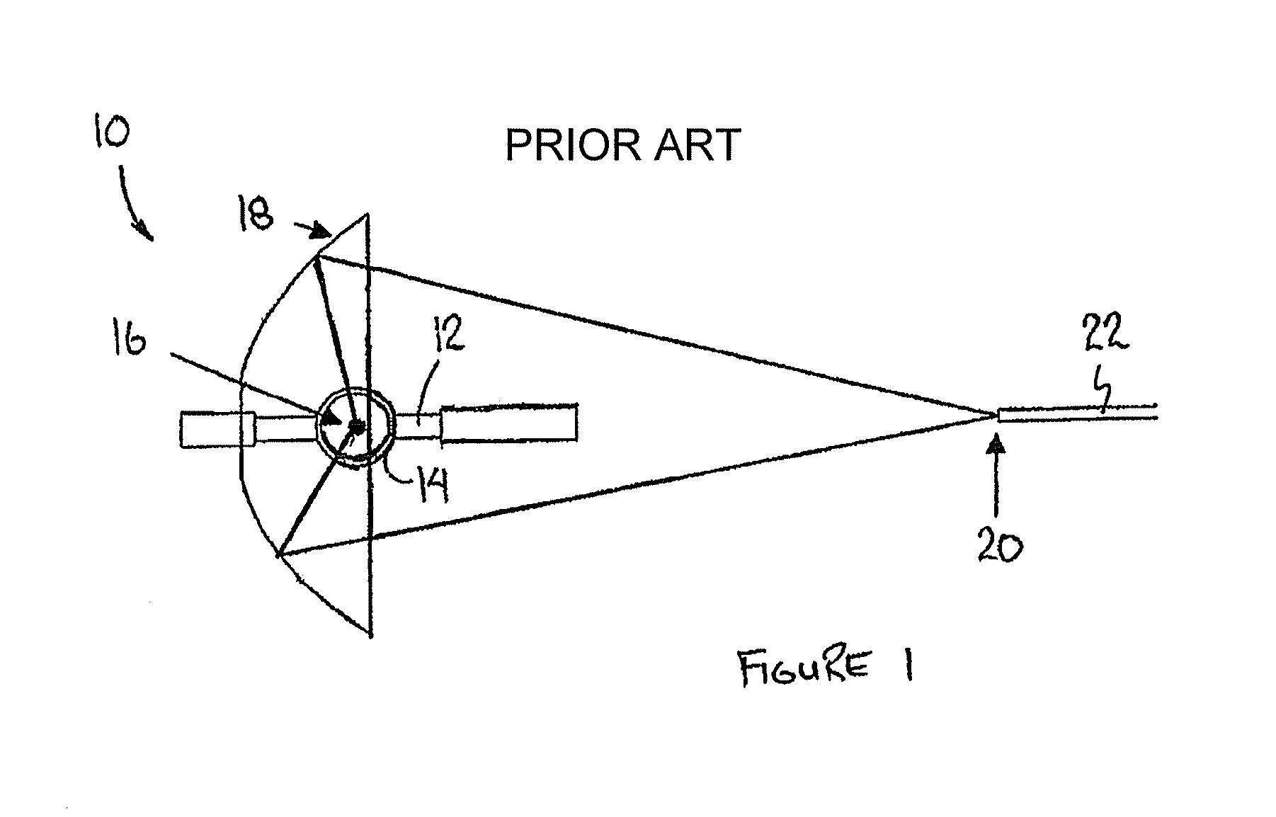
[0027]FIG. 1 shows the general operating principle of a typical lamp projector 10. As shown, light is first generated by the lamp 12 having a bulb 14 located at a first focal point 16 of ellipsoid reflector 18. Light is then re-imaged at a second focal point 20 that is co-incident with a further optics component 22, such as a film projector lens or integrator rod.

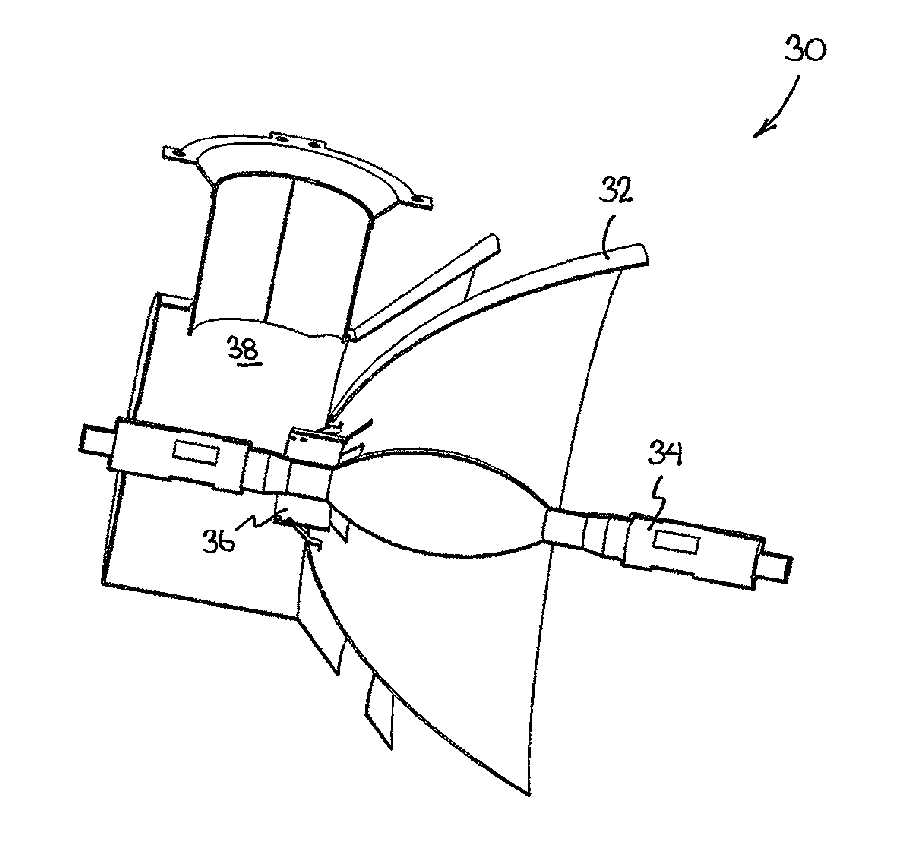
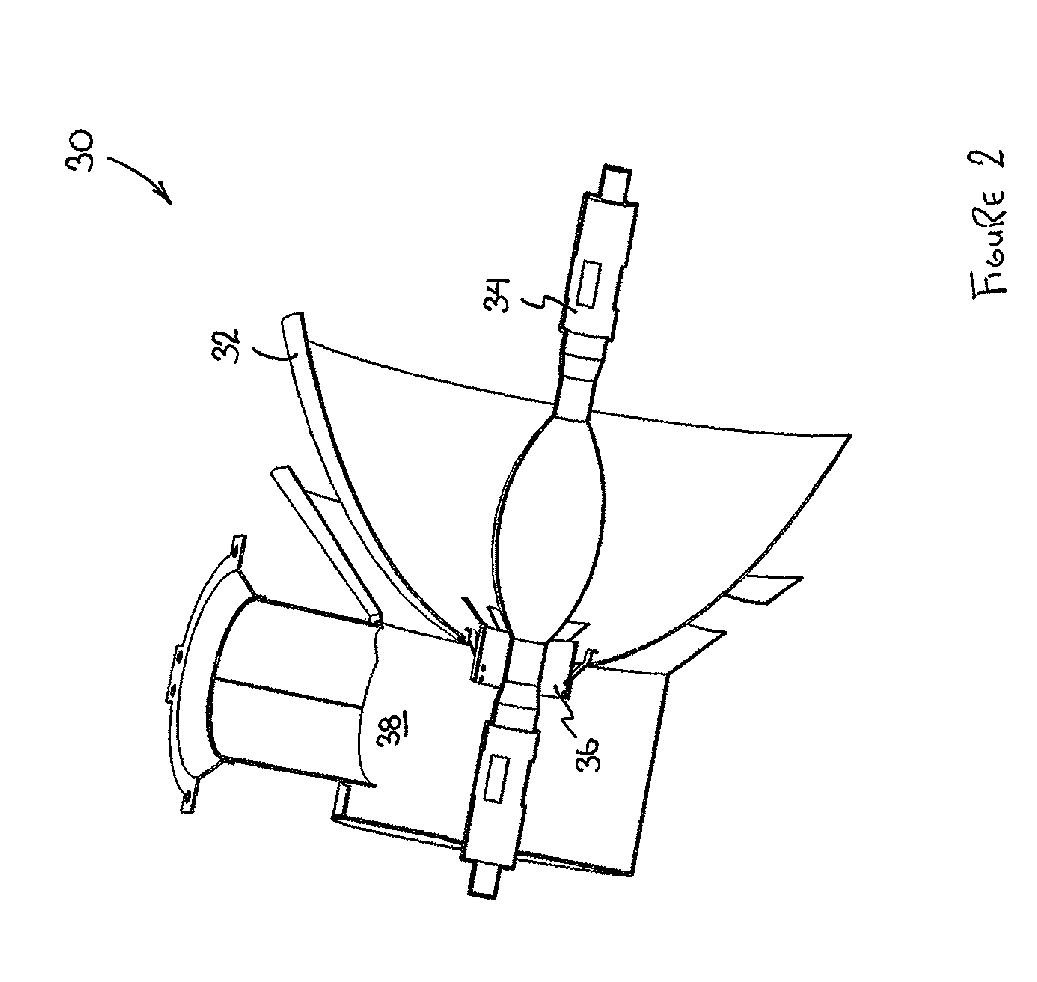
[0028]Referring now to FIG. 2, a projector assembly is indicated generally by the numeral 30. The projector assembly 30 includes an ellipsoid reflector 32, and a lamp 34, as well as a cooperating cooling assembly comprising an air deflector 36, and a main blower duct 38. In the present embodiment, the lamp 34 is a Xenon (Xe) lamp. As shown in FIGS. 3 and 4, the projector assembly 30 is mounted in a housing 40 that facilitates placement of the projector assembly into a projector console cabinet 42, as shown in FIG. 5.

[0029]The housing 40 includes a support frame 44, a reflector mounting plate 46 and a housing cover 48. As be...


PUM


Abstract

In a projector assembly having a lamp for emitting light, and an ellipsoid reflector for capturing the light, the ellipsoid reflector having an opening through its vertex facilitating placement of the lamp, there is provided an improvement wherein the opening in the ellipsoid reflector is sized to allow a major portion of cooling air to pass therethrough into a region defined by the ellipsoid reflector. An air deflector is situated in the opening so as to facilitate distribution of cooling air along the lamp and outwardly towards the inside surface of said ellipsoid reflector from within said region.

Description

FIELD OF THE INVENTION[0001]The present invention relates to a cooling system for use with high performance reflectors and lamps in Film Projector Systems.BACKGROUND OF THE INVENTION[0002]High-end film projector systems typically use Xe bubble lamps coupled to an ellipsoid reflector. The reflected light is captured from the first focal point of the reflector and is re-imaged at the second focal point. The second focal point is commonly co-incident with an optics component such as an integrator rod, film projector lens, etc., depending on the implementation.[0003]Reflectors used for lamps in the 1 to 6 KW range are typically made of metal (e.g. nickel deposit) or glass. Along with reflecting visible light, the reflectors also serve the purpose of removing infrared light generated by the lamp from the second focal point. This helps in reducing the amount of heating within the projector and is vital for projector performance. With metal reflectors this is accomplished by using IR absor...

Claims


Application Information

Patent Timeline
Patent Type & Authority Patents(United States)
IPC IPC(8): G03B21/18F21V29/00F21V7/20G03B21/16F21V29/505
CPCG03B21/16
Inventor GHOSH, ASHIS RANJAN
Owner CHRISTIE SA
Learn More