Dense phase pump with open loop control

a pump and open loop technology, applied in the field of pumps, can solve the problems of overall pump failure, back pressure and other deleterious effects, and special challenges in the application of dry particulate materials,

Inactive Publication Date: 2010-06-08
NORDSON CORP
View PDF40 Cites 16 Cited by
  • Summary
  • Abstract
  • Description
  • Claims
  • Application Information

AI Technical Summary

Problems solved by technology

The application of dry particulate material is especially challenging on a number of different levels.
In order to achieve adequate powder flow rates (in pounds per minute or pounds per hour for example), the components that make up the flow path must be large enough to accommodate the flow with such high air to material (in other words lean flow) otherwise significant back pressure and other deleterious effects can occur.
The overall pump, however, in some cases may be less than optimal for purging, cleaning, color change, maintenance and material flow rate control.

Method used


Image

  • Dense phase pump with open loop control
  • Dense phase pump with open loop control
  • Dense phase pump with open loop control

Examples


Embodiment Construction

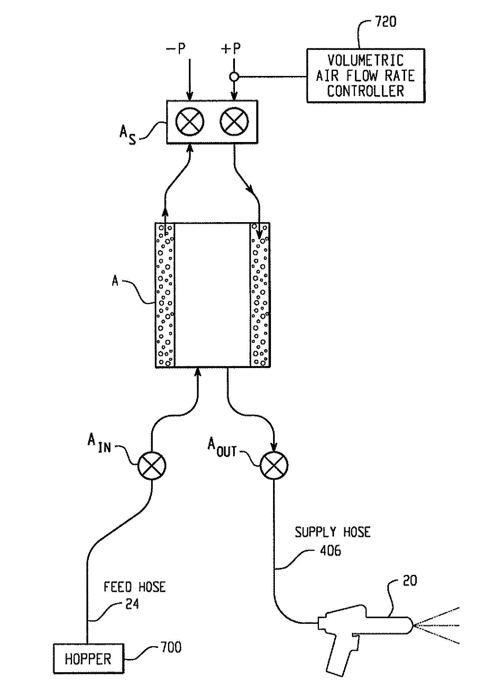
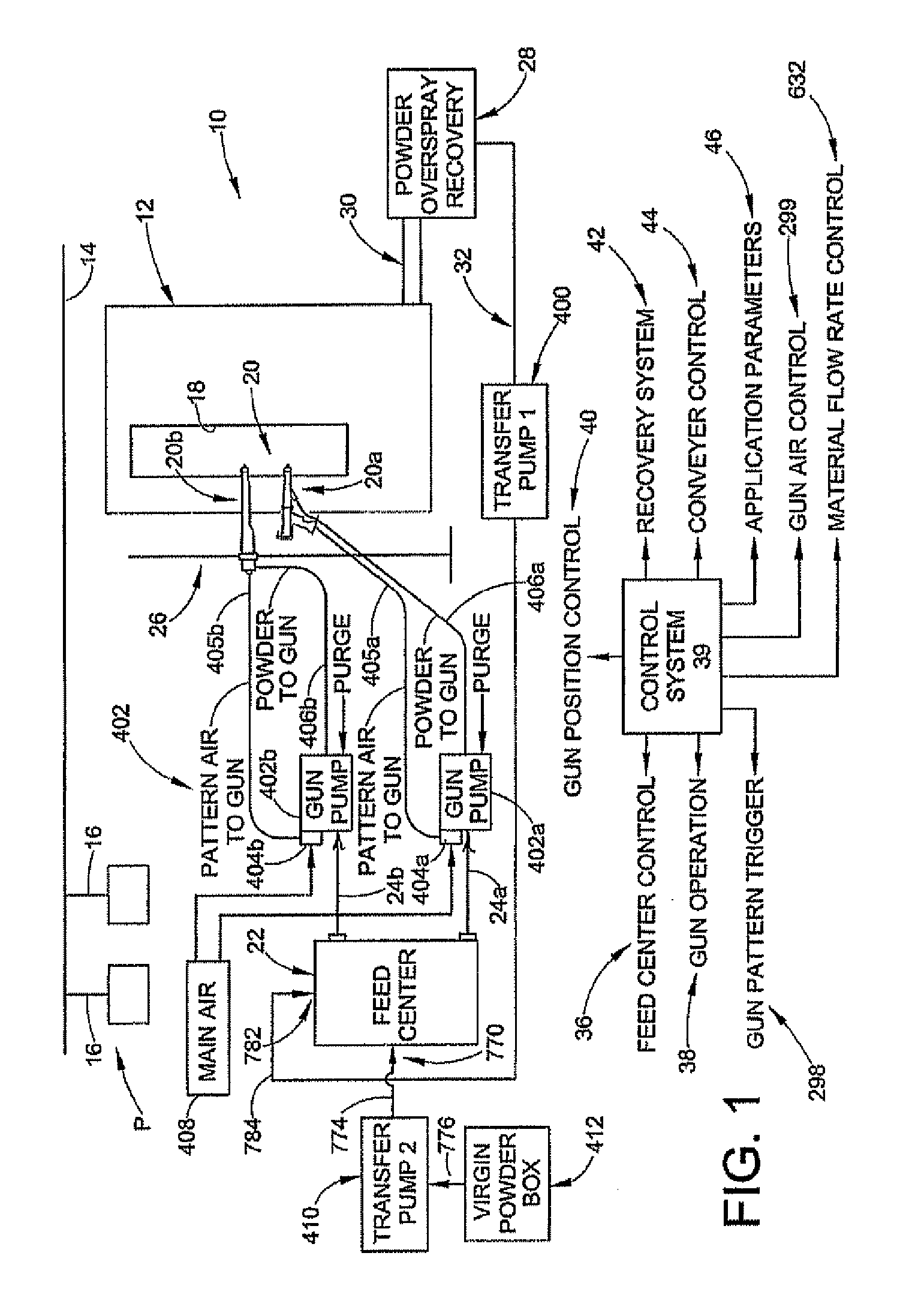
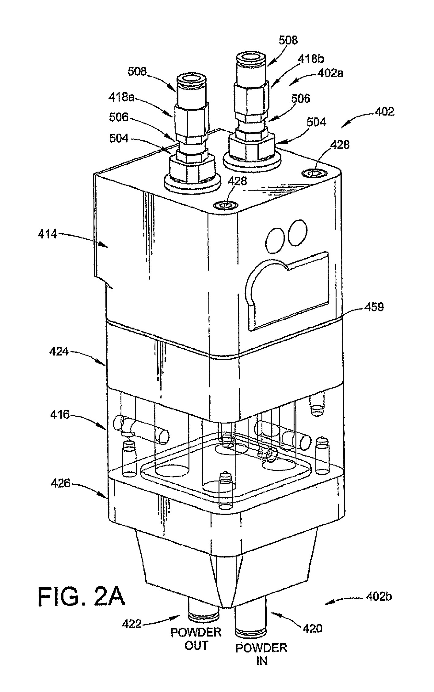
[0037]The inventions contemplate a number of new aspects for a dense phase pump for particulate material. The pump may be used in combination with any number or type of spray applicator devices or spray guns and material supply. One or more of the various inventive aspects or concepts may find application in other pump designs, such as dilute phase pumps.

[0038]By “dense phase” is meant that the air present in the particulate flow is about the same as the amount of air used to fluidize the material at the supply such as a feed hopper. As used herein, “dense phase” and “high density” are used to convey the same idea of a low air volume mode of material flow in a pneumatic conveying system where not all of the material particles are carried in suspension. In such a dense phase system, the material is forced along a flow path by significantly less air volume as compared to a conventional dilute phase system, with the material flowing more in the nature of plugs that push each other alon...


PUM


Abstract

A pump for particulate material includes a pump chamber wherein material flows into the pump chamber under negative pressure and flows out of the pump chamber under positive pressure. A plurality of pinch valves are provided to control flow of material into and out of the pump chamber. The pinch valves are operated independent of each other and of the pump cycle rate. A modular design of the pump is provided. A pump control feature is provided for air flow rate control during positive and negative pressure conditions.

Description

RELATED APPLICATIONS[0001]This application claims the benefit of U.S. Provisional patent application Ser. No. 60 / 725,002 filed on Oct. 7, 2005, for DENSE PHASE PUMP IMPROVEMENTS, the entire disclosure of which is fully incorporated herein by reference.TECHNICAL FIELD OF THE INVENTION[0002]The inventions relate generally to material application and transfer systems, for example but not limited to powder coating material application systems. More particularly, the inventions relate to a pump and pump control functions for such systems.BACKGROUND OF THE INVENTION[0003]Material application systems are used to apply one or more materials in one or more layers to an object. General examples are powder coating systems, other particulate material application systems such as may be used in the food processing and chemical industries. These are but a few examples of a wide and numerous variety of systems used to apply particulate materials to an object.[0004]The application of dry particulate...

Claims


Application Information

Patent Timeline
Patent Type & Authority Patents(United States)
IPC IPC(8): B65G53/58
CPCB05B7/1454B05B7/1459B05B12/00B65G53/28A01D87/10B05B12/02B65G53/525
Inventor FULKERSON, TERRENCE M.NEMETHY, STEPHEN G.THOMPSON, TERRY JOHNPERKINS, JEFFREY A.SCHROEDER, JOSEPH G.
Owner NORDSON CORP
Why Eureka
Try Eureka