Blade and receptacle power connector

a power connector and receptacle technology, applied in the direction of coupling device connection, incorrect coupling prevention, securing/insulating coupling contact member, etc., can solve the problems of currently no mounted connectors, components cannot operate as intended, etc., to achieve easy disengagement, reliable and effective power source, and enhance the ability to repair or replace circuit boards or other components

Active Publication Date: 2010-06-08
TYCO ELECTRONICS LOGISTICS AG (CH)
View PDF22 Cites 17 Cited by
  • Summary
  • Abstract
  • Description
  • Claims
  • Application Information

AI Technical Summary

Benefits of technology

[0006]The contact receiving cavities may have latch arm projections and retention shoulders which extend into securing sections of the contact receiving cavities. The latch arm projections and the retention shoulders cooperate with mounting shoulders of the contacts to retain the contacts in the contact receiving cavities. The latch arm projections may be provided on contact latch arms which can be resiliently displaced to move the latch arm projections out of the contact receiving cavities, thereby allowing the contacts to be removed from the contact receiving cavities.
[0009]The use of the connector has many advantages, including the ability to provide power to a string of circuit boards or other systems using mating connectors already used on the circuit boards. The use of the connector also eliminates the user's need to solder power leads to the circuit board, thereby providing a much more reliable and effective source of power. As the connector can be easily disengaged when desired, the ability to repair or replace the circuit boards or other components is enhanced.

Problems solved by technology

That is, if there is an insufficient electrical connection between the contacts, the components cannot operate as intended.
While the connector assemblies provide an effective connection between panel members, there are currently no mounted connectors which will mate with the connector assemblies to connect power wires to the connector assemblies.

Method used


Image

  • Blade and receptacle power connector
  • Blade and receptacle power connector
  • Blade and receptacle power connector

Examples


Embodiment Construction

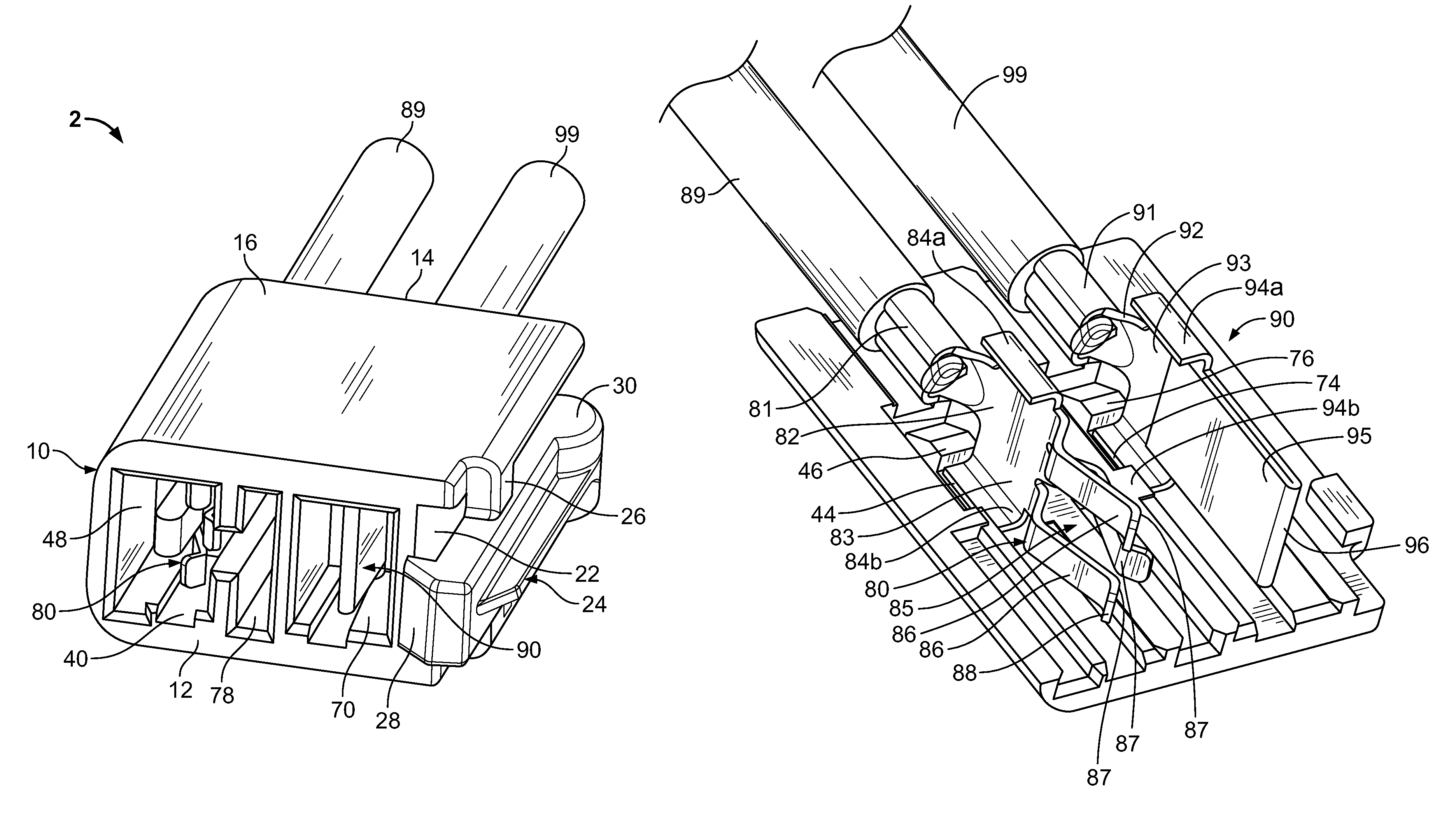
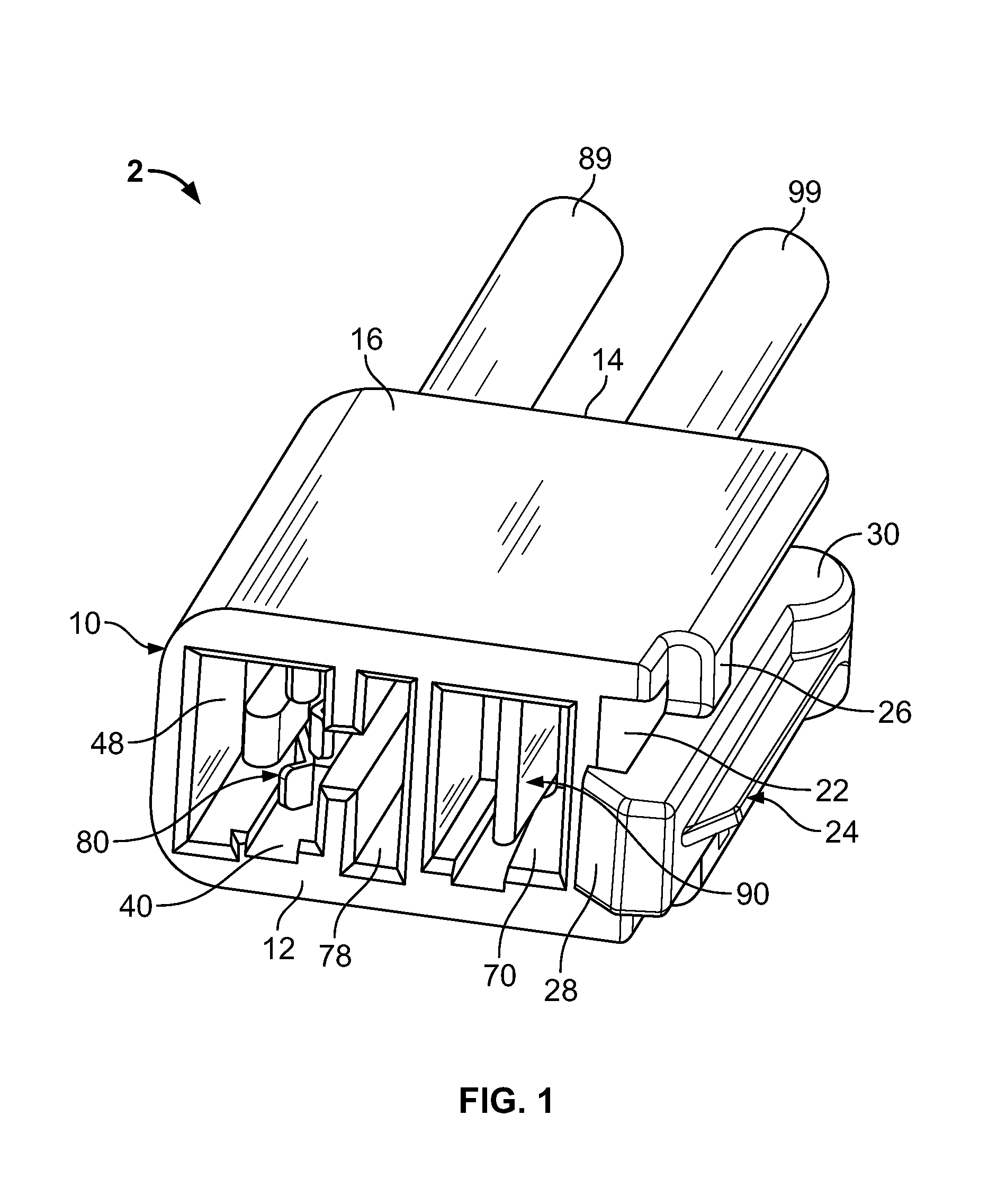
[0019]Referring to FIGS. 1 and 6, a plug connector 2 has a housing 10 with a receptacle contact 80 and a blade contact 90 positioned therein. The housing 10 has a mating face 12 and an oppositely facing wire-receiving face 14. A first wall 16, an oppositely facing second wall 18 (FIG. 5), a first sidewall 20 and a second sidewall 22 extend from the mating face 12 to the wire-receiving face 14. As best shown in FIG. 1, a connector latching arm 24 is provided proximate second sidewall 22. The connector latching arm 24 has pivot members 26 which extend from the first wall 16 and the second wall 18. The pivot members 26 are positioned proximate the longitudinal center of the connector latching arm 24 to allow the connector latching arm 24 to pivot thereabout. A latching projection 28 is provided at an end of the connector latching arm 24 that is positioned proximate the mating face 12. A disengaging member 30 is provided at the opposite end of the connector latching arm 24.

[0020]As best...


PUM


Abstract

An electrical connector for supplying power to a circuit board or the like. The electrical connector has a housing with contact receiving cavities extending from a wire-receiving face to a mating face. Alignment cavities are positioned adjacent the contact receiving cavities and extend from the mating face toward the wire-receiving face. Contacts are positioned in the contact receiving cavities. Each contact has a wire-receiving portion and a contact section. The wire-receiving portion has power wires terminated thereto, and the contact section is positioned in the contact receiving cavities proximate the mating face. A connector latch arm extends from the housing and has a latch projection provided proximate the mating face of the housing. The latch projection is movable relative to the housing.

Description

FIELD OF THE INVENTION[0001]The present invention relates generally to electrical power connector assemblies and, more particularly, to electrical power connector assemblies for use with electrical panel members.BACKGROUND OF THE INVENTION[0002]Connector assemblies are required to provide electrical power or electrical or electronic control signals between components, such as computers, printers, auxiliary hardware, etc. Often, these components contain panel members, such as printed circuit boards, which are populated with miniaturized components to provide the desired electrical control. Typically, the connector assembly includes electrical contacts that extend from a housing that is secured adjacent to one end of the panel member. A mating connector assembly is configured for receiving the connector assembly. The operational reliability of the component is directly affected by the integrity of the connection. That is, if there is an insufficient electrical connection between the c...

Claims


Application Information

Patent Timeline
Patent Type & Authority Patents(United States)
IPC IPC(8): H01R13/627H01R24/58
CPCH01R23/27H01R13/6272H01R24/84
Inventor DAILY, CHRISTOPHER GEORGEMOSTOLLER, MATTHEW EDWARDFISHER, SETH
Owner TYCO ELECTRONICS LOGISTICS AG (CH)
Why Eureka
Try Eureka