System and method for heating carbon fiber using infrared radiation in a fiber placement machine

a technology of infrared radiation and fiber placement machine, which is applied in the direction of document inserters, printing, chemistry apparatus and processes, etc., can solve the problems of inability to heat carbon fiber, and inability to meet the needs of the user, etc., to achieve the effect of quick heat of a tool or a previously laid tow, easy control, and low cos

Active Publication Date: 2010-06-08
INGERSOLL MACHINE TOOLS
View PDF42 Cites 79 Cited by
  • Summary
  • Abstract
  • Description
  • Claims
  • Application Information

AI Technical Summary

Benefits of technology

[0008]In one aspect, a heating apparatus, system and method that may be used with a fiber placement machine to quickly heat a tool or previously laid tows proximate an application area or a point of compaction is provided. The heating is provided by an infrared (IR) heater. Such a system and method is inexpensive, quick to react, easy to control, and requires fewer assembly components compared to conventional systems.

Problems solved by technology

The heat supplied to the tows causes them to become tacky (a.k.a., sticky).
Unfortunately, the fiber placement machinery today is limited in its use partially due to the inability to quickly heat the tool or the carbon fiber tows proximate the point of application and compaction.
Previous methods of heating require complex, expensive assemblies and use the heat transfer method of convection.
Blowing hot air in the direction of the tool or the previously laid tows is a somewhat effective heating method, but it is slow reacting and is much more difficult to control.

Method used


Image

  • System and method for heating carbon fiber using infrared radiation in a fiber placement machine
  • System and method for heating carbon fiber using infrared radiation in a fiber placement machine
  • System and method for heating carbon fiber using infrared radiation in a fiber placement machine

Examples


Embodiment Construction

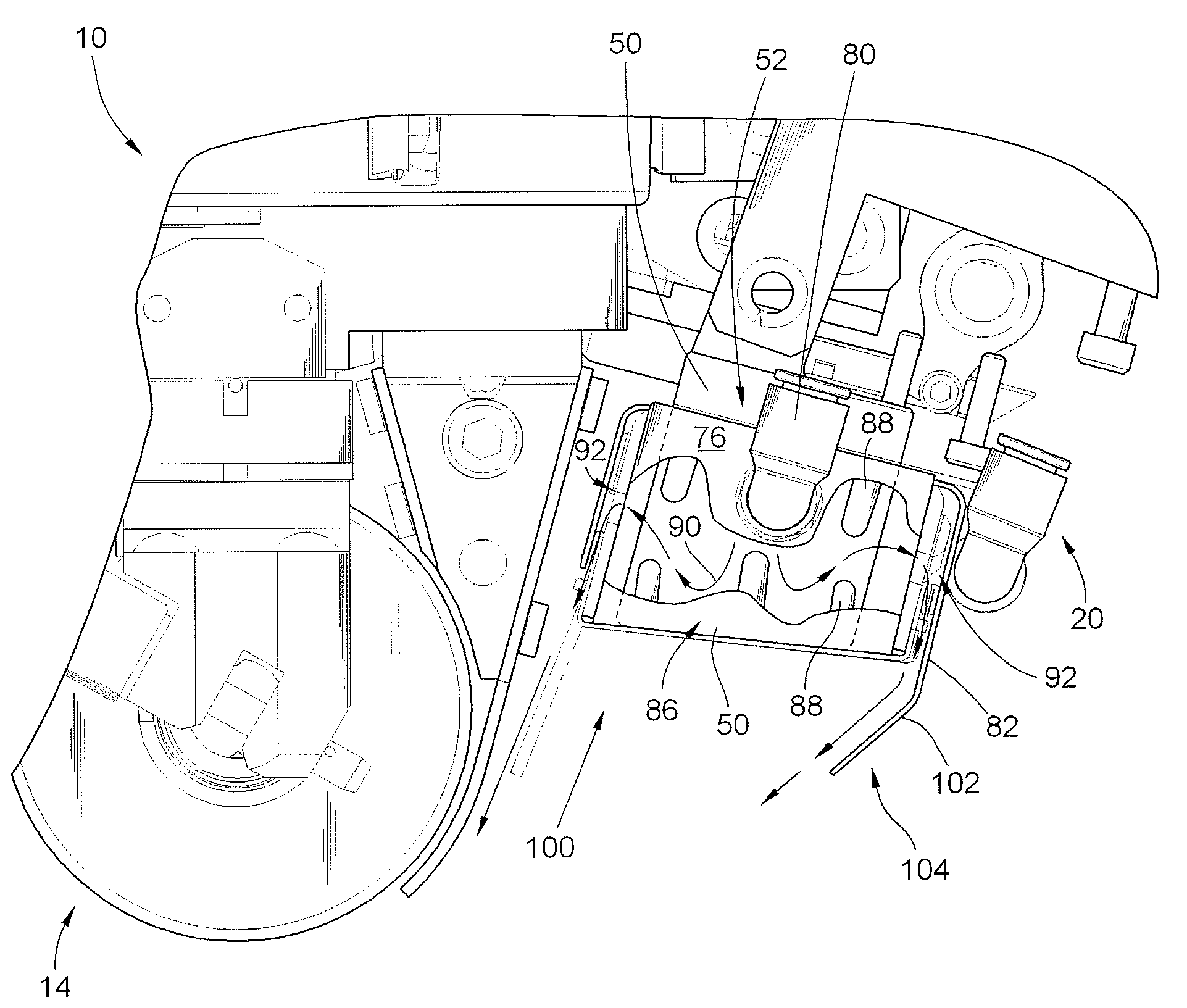
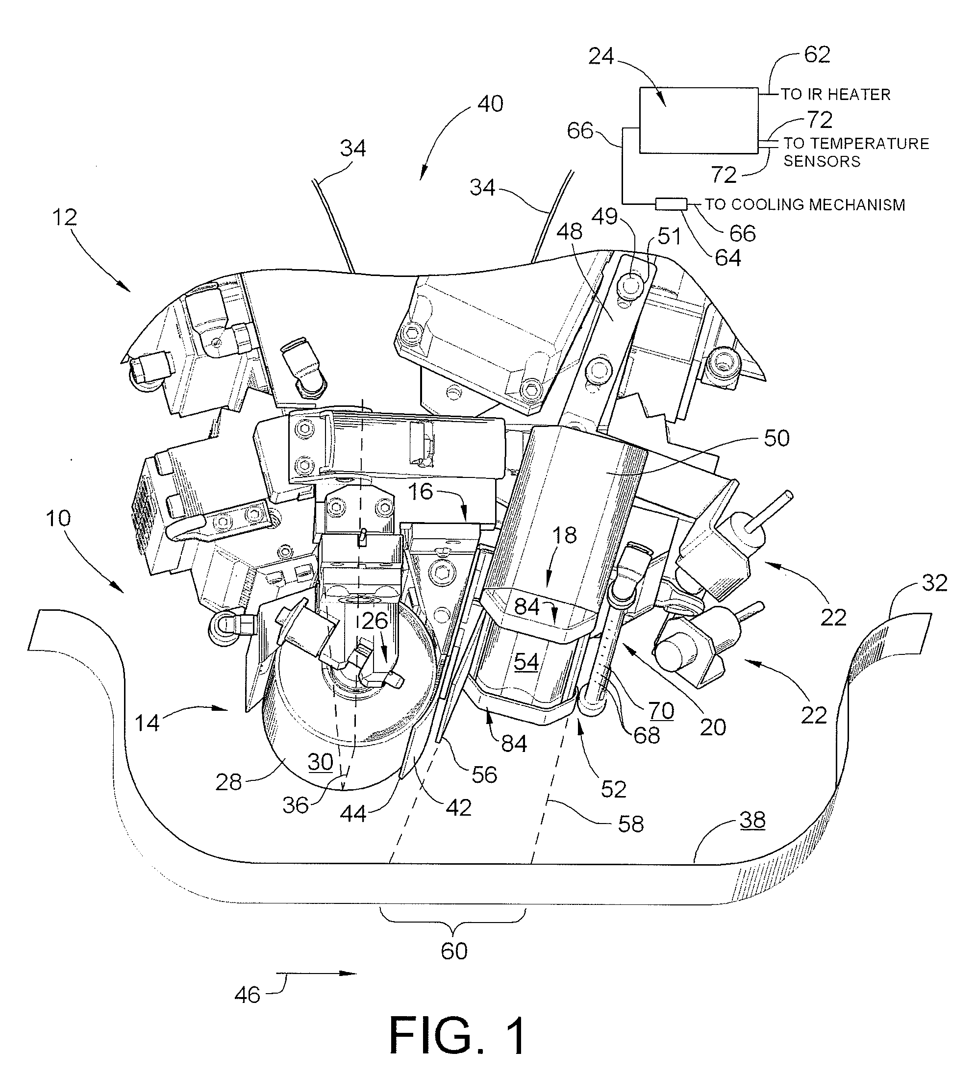
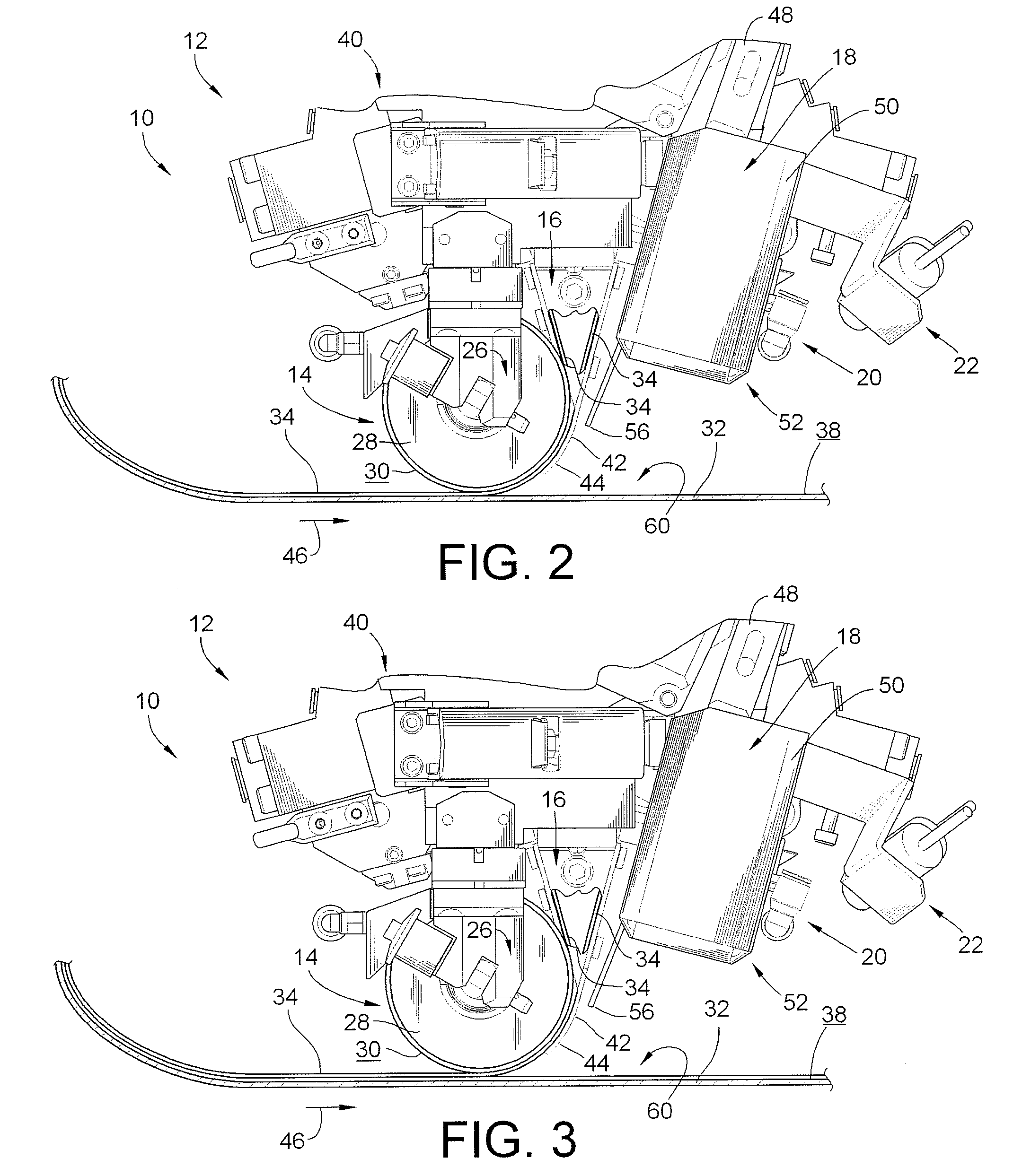
[0017]As illustrated in FIG. 1, a fiber placement head assembly 10 for a fiber placement machine 12 constructed in accordance with one embodiment of the present invention is shown. Although not shown, the fiber placement machine 12 is operably coupled to a gantry or other mechanically moveable structure such that the fiber placement head assembly 10 can be steered in a number of directions and maneuvered in several different directions. As will be more fully explained below, an infrared (IR) heating source operably coupled to the fiber placement head assembly 10 supplies heat during a fiber placement operation in a simple and inexpensive manner compared to conventional fiber placement head assemblies that rely on the heat transfer method of convection for heating.

[0018]As shown in FIG. 1, in one embodiment the fiber placement head assembly 10 includes, among numerous other assemblies and subassemblies, a compaction roller assembly 14 and a feeder assembly 16. An infrared heating ass...


PUM

PropertyMeasurementUnit
temperatureaaaaaaaaaa

Abstract

An apparatus comprising a fiber placement head assembly and an infrared heating assembly is provided. The fiber placement head assembly includes a compaction roller assembly and a feeder assembly. An infrared heating assembly, a cooling mechanism, temperature sensors, and a controller are operably coupled to the fiber placement head assembly. The infrared heating assembly includes an infrared heater that generates a heating profile. The heating profile defines a heating zone on either a tool or previously laid tows. If the burn point of either the tool or previously laid tows within the heating zone is approached, the controller, which receives temperature readings from the temperature sensors, simultaneously disables the infrared heater and activates the cooling mechanism. As such, the tool and the previously laid tows are protected from being ruined due to an over temperature condition.

Description

CROSS-REFERENCE TO RELATED PATENT APPLICATIONS[0001]This patent application claims the benefit of U.S. Provisional Patent Application No. 60 / 773,816, filed Feb. 16, 2006, the entire teachings and disclosure of which are hereby incorporated in their entireties by reference thereto.FIELD OF THE INVENTION[0002]This invention generally relates to fiber placement machinery, and more particularly to methods and apparatuses used in such fiber placement machinery to heat the fiber laid thereby.BACKGROUND OF THE INVENTION[0003]Automated fiber placement machines are widely used to manufacture parts, components and structures from composite material. The materials used in automated fiber placement are typically composed of longitudinal fibers and resin consolidated into tapes, or thin strips, commonly known as “tows.” Anywhere from a single tow to several of the tows arranged side-by-side are fed out of the fiber placement machine as the fiber placement machine lays and compacts a “ply” or “co...

Claims


Application Information

Patent Timeline
Patent Type & Authority Patents(United States)
IPC IPC(8): B32B37/00B65H81/00
CPCB29C35/0288B29C70/384B29C2035/0822B29C35/0294
Inventor OLDANI, TINOGOEBEL, DANIEL
Owner INGERSOLL MACHINE TOOLS
Why Eureka
Try Eureka