
Modular housing system for outside plant telecommunications equipment

a technology for telecommunication equipment and modules, applied in the field of remote enclosures for electrical equipment, to achieve the effects of reducing housing development costs, improving reliability, and reducing the number of housing components

Active Publication Date: 2010-06-08
ADTRAN
View PDF18 Cites 7 Cited by
  • Summary
  • Abstract
  • Description
  • Claims
  • Application Information

AI Technical Summary

Benefits of technology

[0007]The problems of the prior art are overcome or at least mitigated through the use of a modular OSP housing system as more particularly described hereinafter. A modular OSP housing system (“housing system”) disclosed herein addresses various problems associated with conventional OSP housings. The problems addressed include having a housing system that is adaptive to meet a variety of implementation requirements. When considering existing and future products the adaptability of the disclosed housing system results in a reduction in the number of housing components (solving a parts proliferation problem). For the new housing system (when compared to conventional housings) there is an improvement in reliability and a reduction in housing development costs.
[0008]The housing system of the disclosure has a modular design and is adaptable to meet the requirements of a variety of products. The new OSP housing system is comprised of a main body such as a main casting and one or more auxiliary bodies or sub-castings. Hence, the housing system may be viewed as blocks that are coupled in different combinations to meet a specific product requirement. Since modules are reusable, manufacturing cost is often spread over several products thereby reducing the cost of a specific product. In addition, further cost reduction is often provided as production volumes increase. Another benefit of the modular design of the housing system is the ability to form a new housing quickly. Since each component module is smaller the tooling is less complex and it is generally quicker to update or modify modules.

Problems solved by technology

The problems addressed include having a housing system that is adaptive to meet a variety of implementation requirements.

Method used


Image

  • Modular housing system for outside plant telecommunications equipment
  • Modular housing system for outside plant telecommunications equipment
  • Modular housing system for outside plant telecommunications equipment

Examples


Embodiment Construction

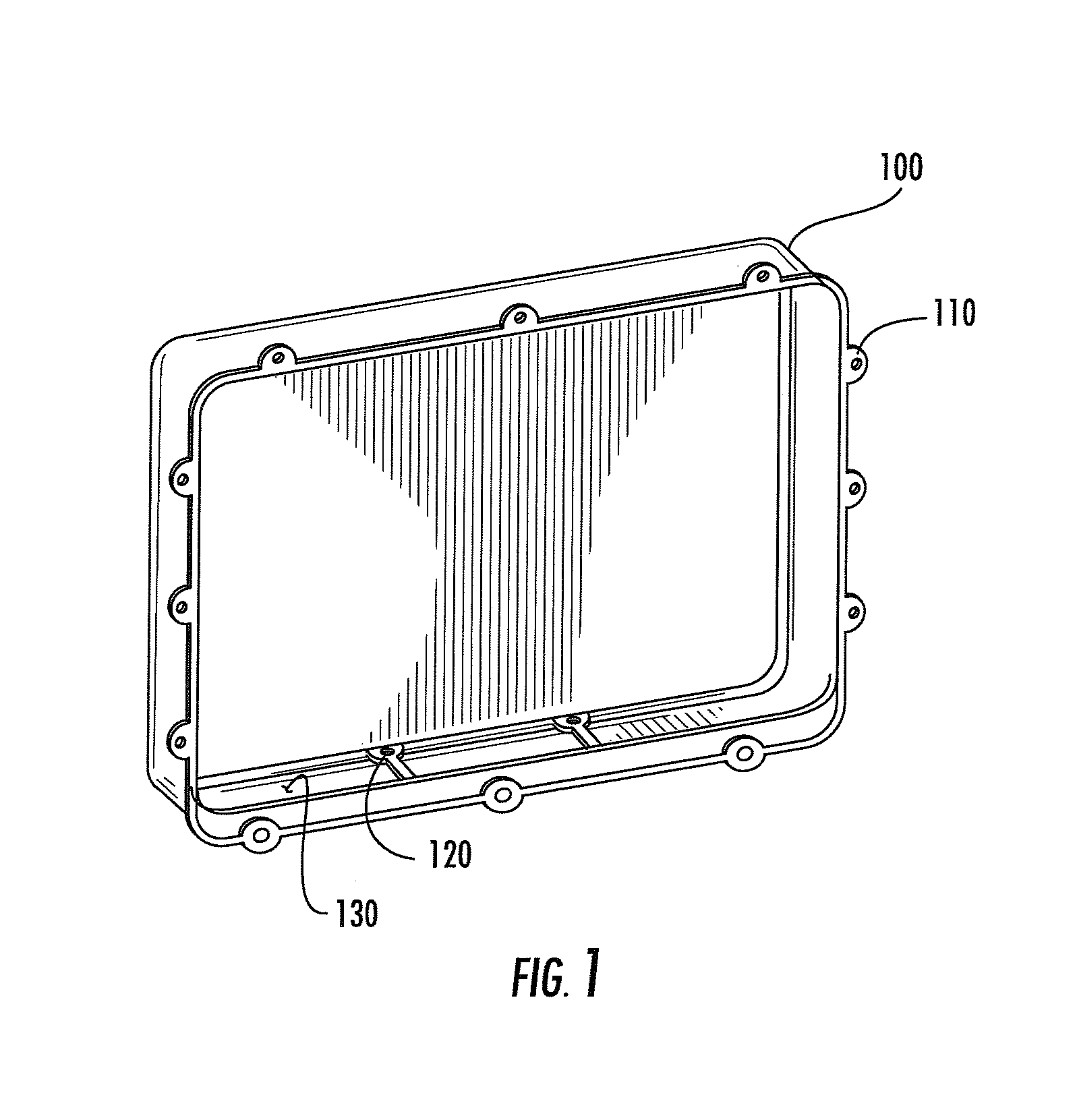
[0018]FIG. 1 shows a front perspective view of a main casting (main body) of an OSP housing in accordance with one aspect of the invention. The housing 100, has the plurality of mounting tabs 110 which are used to secure a cover for the main casting when installed. There are also a plurality of mounting holes 120 which facilitate attachment of a sub-casting to the main casting. Three apertures 130, in this example, enable connections to be made between electronics contained in the sub-casting module to electronic equipment contained in the main casting module 100.

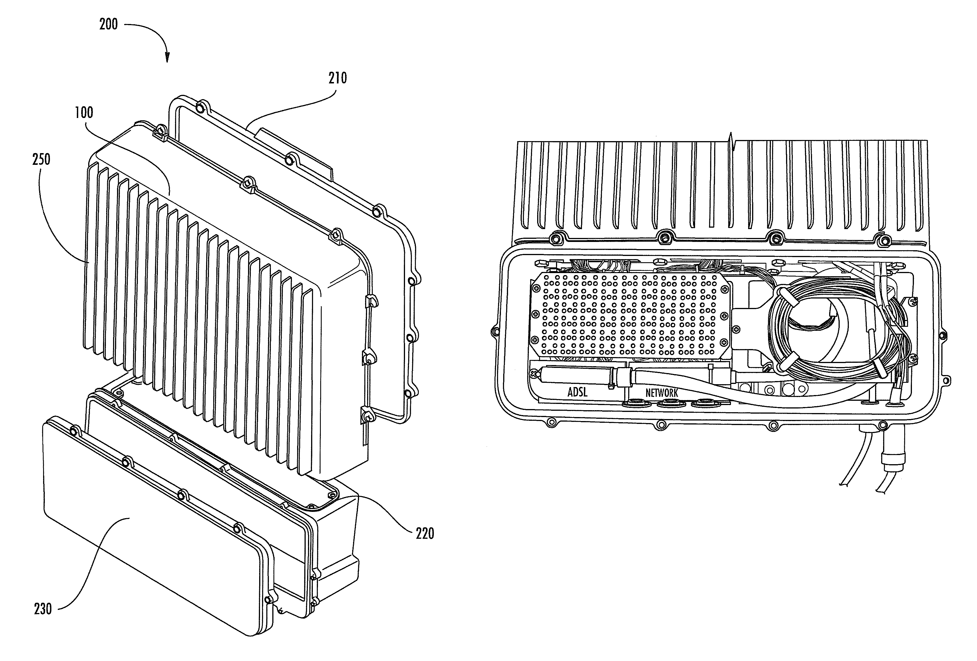
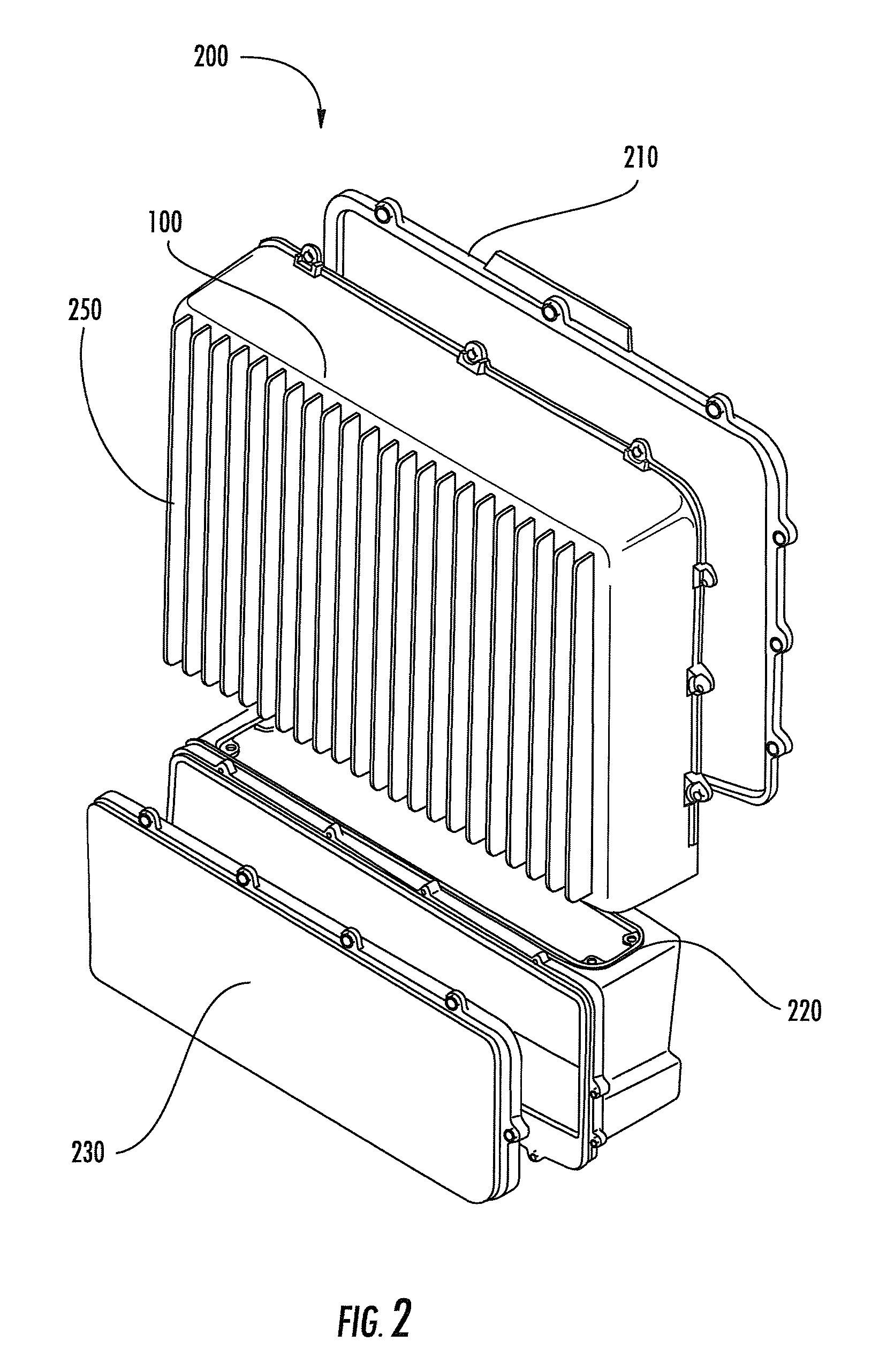
[0019]Turning to FIG. 2, the housing system 200 is comprised of 4 components. The components are:[0020]a main casting 100 for holding Printed Circuit Boards (PCBs) and related electronics.[0021]a main casting cover 210 for sealing an aperture of the main casting.[0022]subcasting 220 (for holding I / O modules), and[0023]subcasting cover 230 for sealing an aperture of the sub-housing.

[0024]The main casting 200 has a cavity enc...


PUM


Abstract

A modular housing for outside plant telecommunication equipment includes a main enclosure for containing common electronic equipment and an auxiliary enclosure for containing input / output (I / O) circuitry to said common electronic equipment. In this way, different configurations of I / O circuitry can be accommodated only by changing the auxiliary enclosure. The design and fabrication times for making housings is reduced by the smaller size of each enclosure. Upgrades can often be accommodated by only changing one of the main or auxiliary housings.

Description

BACKGROUND OF THE INVENTION[0001]1. Field of the Invention[0002]The invention relates to the field of remote enclosures for electrical equipment and, more particularly to improved housings for outside plant (OSP) telecommunications equipment.[0003]2. Description of the Prior Art[0004]Conventional housings for outside plant telecommunication equipment, such as the ADTRAN TA1148 OSP housing, are typically designed for a specific product and generally are product limited. When a service provider, such as a telecommunications company, requires significant changes to an OSP product or a manufacturer introduces a new product, it is often necessary to provide a new OSP housing. When the new housing requires geometric changes (e.g. size, PCB component changes, material thickness, etc.) such changes usually add cost and undesirable manufacturing delay. Hence, a new housing, if required, has undesirable consequences. As a result, there is a need for an improved housing that is readily availab...

Claims


Application Information

Patent Timeline
Patent Type & Authority Patents(United States)
IPC IPC(8): H04M1/00H04M9/00
CPCH04M19/06
Inventor AYRES, III, JOHN WISEKRUSE, GRANT JOSEPH
Owner ADTRAN
Learn More