
Electronic lock box using a biometric identification device

a biometric identification and electronic lock technology, applied in anti-theft devices, programs, instruments, etc., can solve the problems of pins being undesirable, and achieve the effects of enhancing security, facilitating comparison and authorization of lock system functions, and reducing the insecurity of pin codes

Inactive Publication Date: 2010-06-08
SENTRILOCK
View PDF12 Cites 39 Cited by
  • Summary
  • Abstract
  • Description
  • Claims
  • Application Information

AI Technical Summary

Benefits of technology

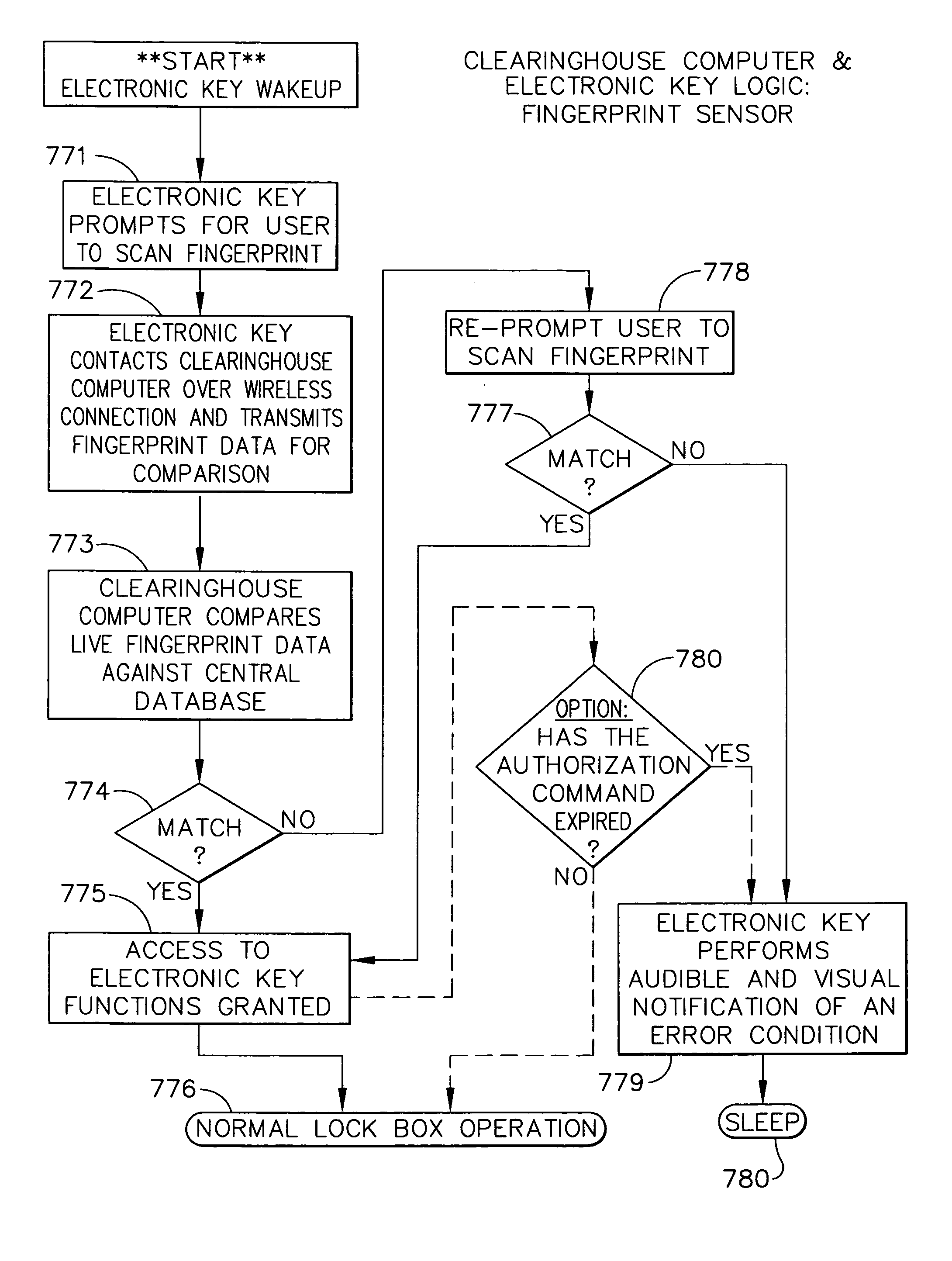
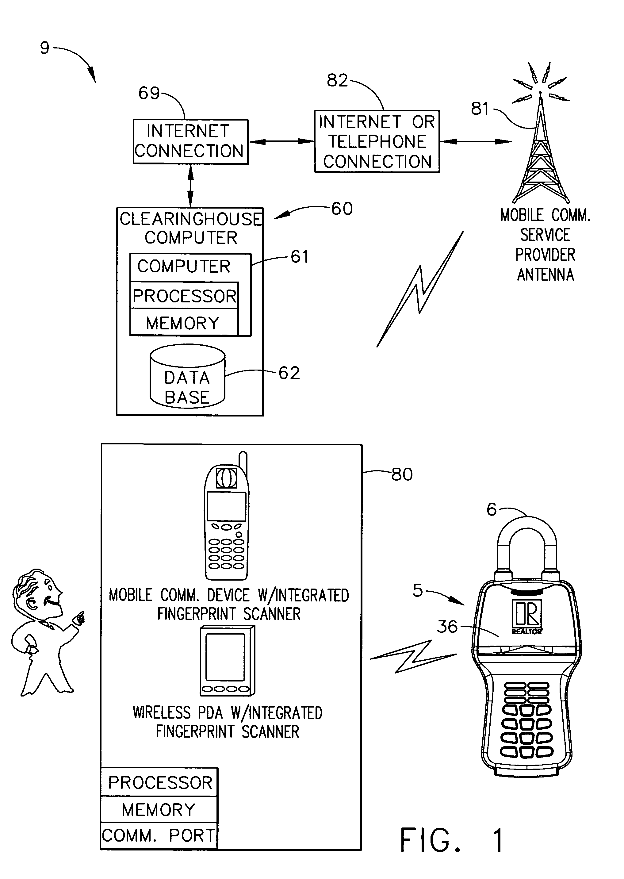
The present invention provides an electronic lock box system with improved security by eliminating the insecurity of PIN code protection and replacing it with biometric identification. The system uses biometric identification data, such as observed facial or fingerprint data, to verify the identity of a user before granting access to the lock box. The system can be implemented in an electronic lock box with a secure compartment, a shackle for attachment to a fixed object, and a processing circuit. The method involves collecting the observed biometric identification data from the user, comparing it to enrollment biometric identification data stored in a database, and transmitting an authorization message from the central computer to the external portable computer if there is a sufficient correlation between the two. The invention provides a safer and more secure electronic lock box system.

Problems solved by technology

PIN's can also be undesirable because the necessity of a fairly short number of digits to satisfy the convenience of memorization by the user leaves the number of possible PIN permutations small, and therefore, fairly easy to guess.

Method used


Image

  • Electronic lock box using a biometric identification device
  • Electronic lock box using a biometric identification device
  • Electronic lock box using a biometric identification device

Examples


Embodiment Construction

[0036]Reference will now be made in detail to the present preferred embodiment of the invention, an example of which is illustrated in the accompanying drawings, wherein like numerals indicate the same elements throughout the views.

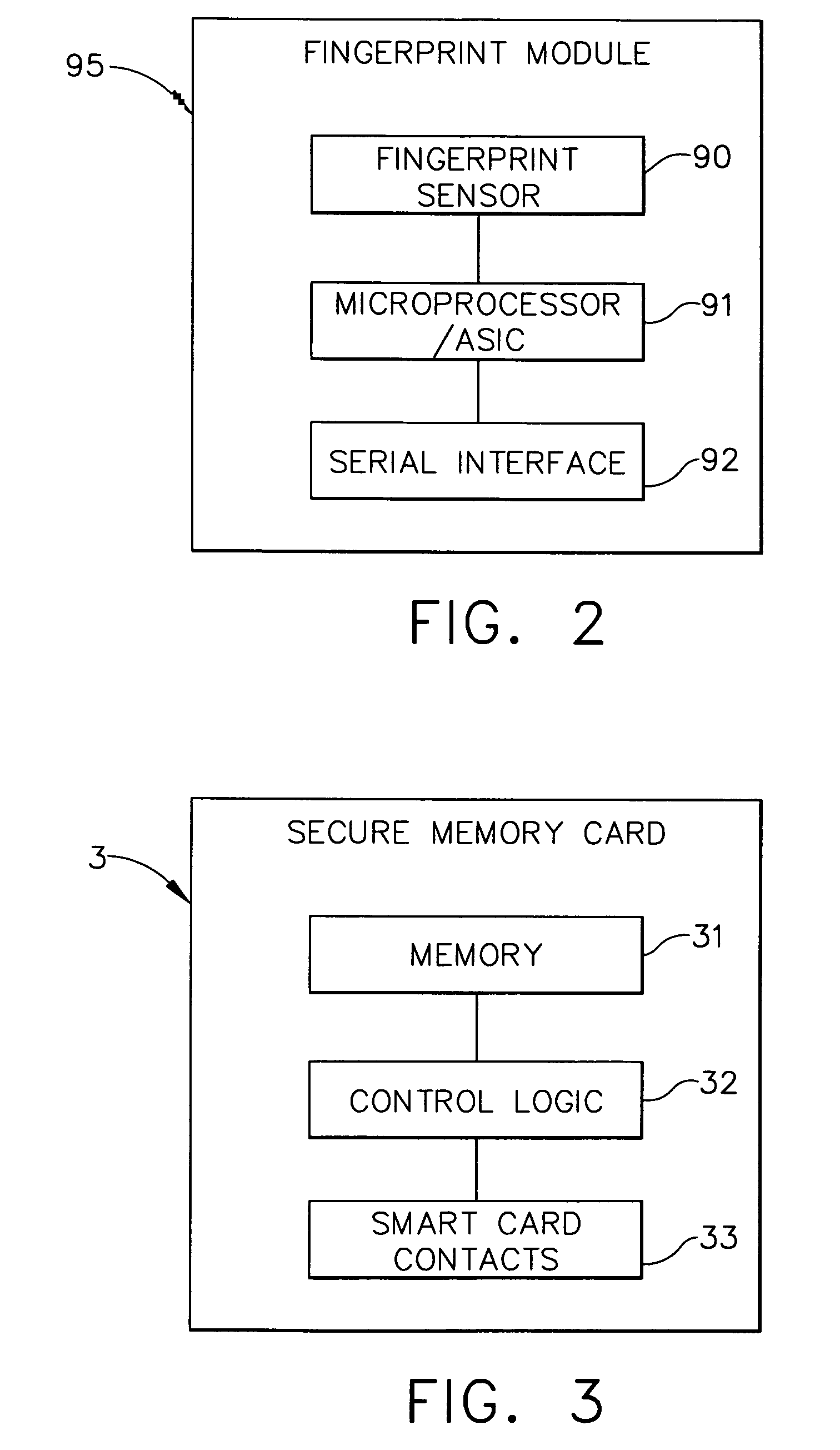
[0037]The present invention supports various distinct electronic lock box access methodologies. One methodology uses a system of conditional access code that are disclosed to the user for controlling electronic lock box key compartment access. The access code is conveyed securely from the electronic lock box to a portable computer via a secure memory device (also referred to as a “secure memory card”); moreover, the access code is generated as a random number (by the electronic lock box) and is generated in real time as the attempted access is in progress. Depending on expiration status and other factors, the portable computer determines whether the electronic lock box access code should be revealed to the user. The portable computer, in this embodiment, ...


PUM


Abstract

An improved electronic lock box system is provided for more secure control over the accessibility of a secure compartment in the electronic lock box, which is typically used to store a dwelling key. The new system uses biometric identification sensors to determine if the correct, authorized user is attempting to access the secure compartment of the electronic lock box. In one embodiment, the biometric identification sensor uses thermal scanning to detect a person's fingerprint pattern. This is compared to previously stored (enrollment) biometric identification information / data, and if the “live” (observed) biometric identification information / data sufficiently correlates to the stored enrollment biometric identification information / data, access will be granted.

Description

CROSS-REFERENCE TO RELATED APPLICATIONS[0001]The present application claims priority to provisional patent application Ser. No. 60 / 730,536, titled “ELECTRONIC LOCK BOX WITH BIOMETRIC IDENTIFICATION DEVICE,” filed on Oct. 26, 2005.TECHNICAL FIELD[0002]The present invention relates generally to electronic lock equipment and is particularly directed to an electronic lock box of the type that contains a secure compartment for storing keys that allow entry to a structure or other objects. The invention is specifically disclosed as an electronic lock box system that uses biometric sensors to determine if the correct, authorized user is attempting to access the secure compartment of the electronic lock box. In one embodiment, the biometric sensor uses thermal scanning to detect a person's fingerprint pattern.BACKGROUND OF THE INVENTION[0003]All of the real estate electronic lock box systems in use today guard against unauthorized use by requiring the real estate agent to enter a personal i...

Claims


Application Information

Patent Timeline
Patent Type & Authority Patents(United States)
IPC IPC(8): G06K9/00
CPCE05B19/0005G06K9/00006G07C9/00087G07C9/00896G07C9/00563G07C9/00103G07C2009/00936G07C9/00817G07C2009/00095G07C9/26G07C9/257G07C9/27G07C9/21G06V40/12
Inventor FISHER, SCOTT R.
Owner SENTRILOCK
Learn More