Single fibre bidirectional optical transmission system and single fibre bidirectional optical amplifier

a transmission system and optical amplifier technology, applied in the field of single fibre bidirectional optical transmission system and single fibre bidirectional optical amplifier, can solve the problems of large consumption power, large device size, high cost,

Active Publication Date: 2010-06-08
NEC CORP
View PDF24 Cites 10 Cited by
  • Summary
  • Abstract
  • Description
  • Claims
  • Application Information

AI Technical Summary

Problems solved by technology

This makes the cost expensive and the device size large, and causes a problem in that the consumption power becomes large and the like.
Therefore, it is necessary to newly develop an element for exclusive use of the single fibre bidirectional optical amplifier, and this causes a problem in that the cost becomes expensive.
Consequently, there aris

Method used


Image

  • Single fibre bidirectional optical transmission system and single fibre bidirectional optical amplifier
  • Single fibre bidirectional optical transmission system and single fibre bidirectional optical amplifier
  • Single fibre bidirectional optical transmission system and single fibre bidirectional optical amplifier

Examples


first embodiment

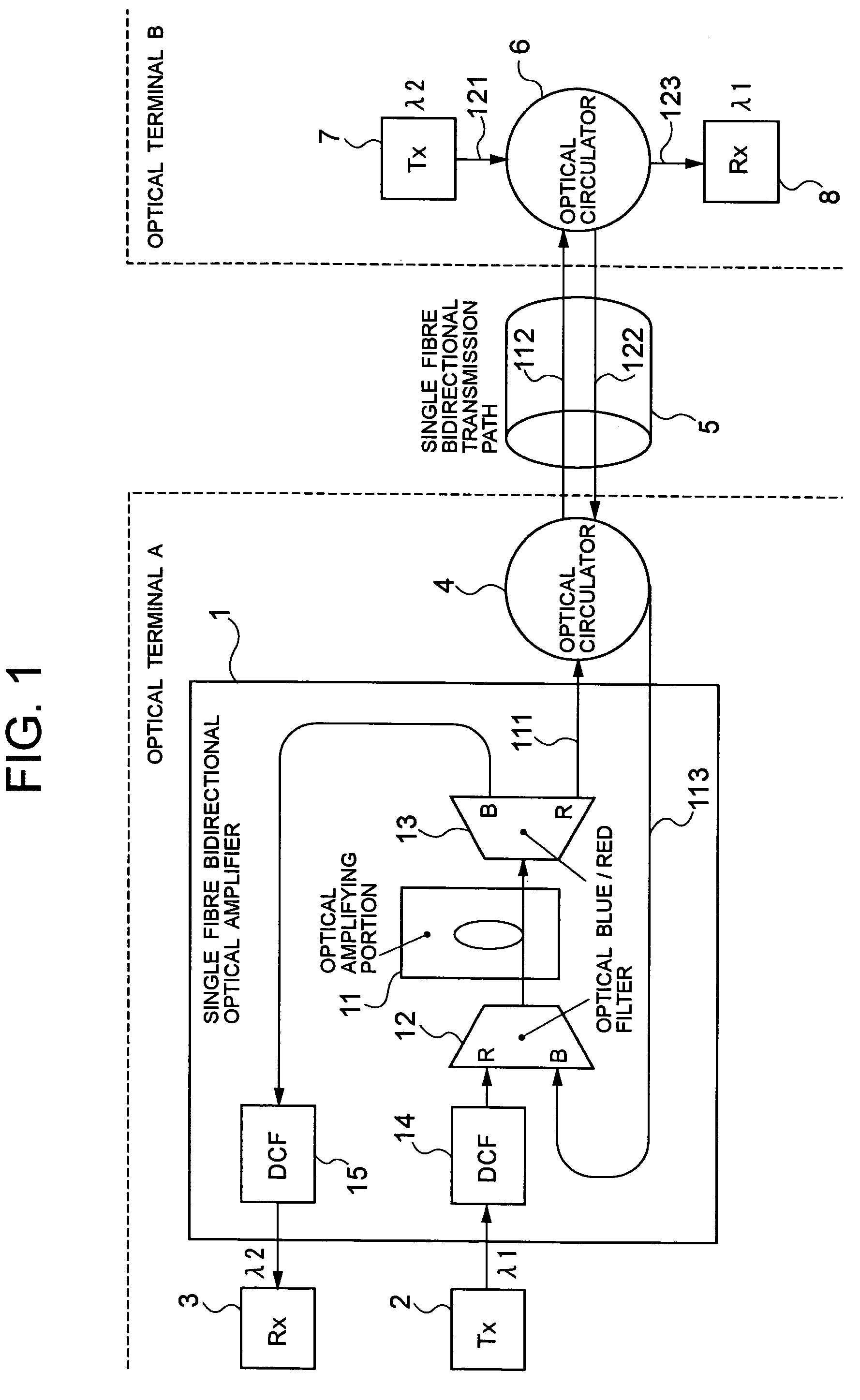
[0055]Next, embodiments of the present invention will be described with reference to the drawings. FIG. 1 is a block diagram showing the configuration of a single fibre bidirectional optical transmission system according to the present invention. In FIG. 1, one optical terminal A of a transmission path is configured by a single fibre bidirectional optical amplifier 1, a first optical transmitter (Tx) 2, and a first optical receiver (Rx) 3, and is connected to a single fibre bidirectional transmission path 5 through an optical circulator 4.

[0056]The other optical terminal B of the transmission path is configured by a second optical transmitter (Tx) 7 and a second optical receiver (Rx) 8, and is connected to the single fibre bidirectional transmission path 5 with a single-mode fibre through an optical circulator 6.

[0057]The single fibre bidirectional optical amplifier 1 comprises an optical amplifying portion 11 (for example, erbium doped fibre amplifying portion), an optical Blue / Red...

second embodiment

[0086]At this time, in the present embodiment, similarly with the above-described second embodiment of the present invention, the optical circulators 4 and 6 can use the optical Blue / Red filter having the same band as the optical Blue / Red filters 12 and 13.

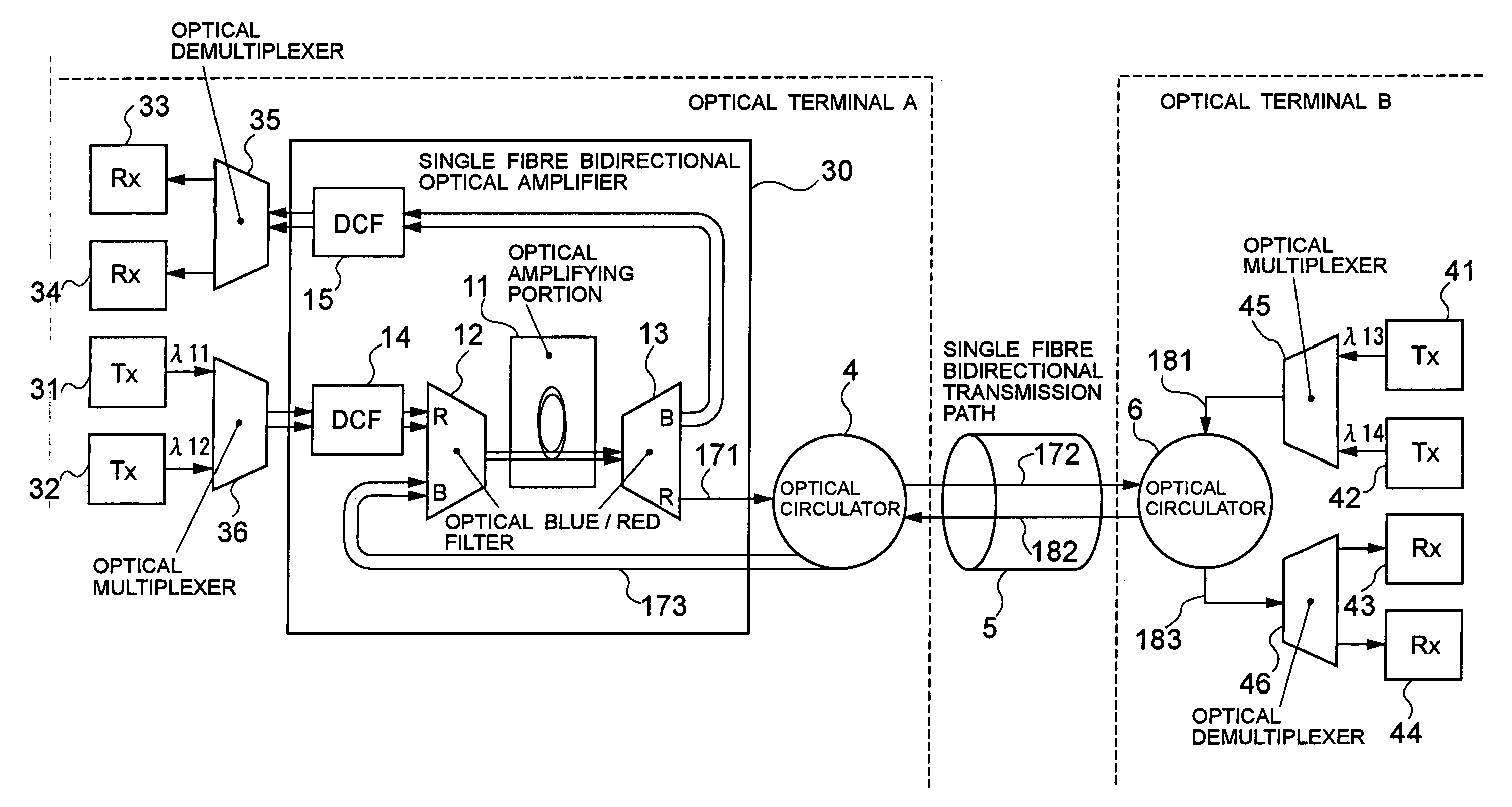
[0087]Further, the frequency of each signal from the wavelength λ11 to the wavelength λ14 is 192.30 THz, 192.50 THz, 194.60 THz and 194.40 THz, respectively. As the frequency arrangement of the signal beams λ11 to λ14 is shown in FIG. 11, since the wavelengths λ11 and λ12, and the wavelengths λ13 and λ14 can be divided into separate ports by the optical interleaver 37, the optical circulators 4 and 6 can be realized even by the optical interleavers similarly with the above-described third embodiment of the present invention. Further, in the present embodiment, similarly with the above-described fourth embodiment of the present invention, the optical Blue / Red filters 12 and 13 within the single fibre bidirectional amplifier 30 may ...


PUM


Abstract

The present invention provides a single fiber bidirectional optical transmission system capable of realizing the extension of a single fiber bidirectional long distance at a moderate price.
An optical signal outputted from a second optical transmitter is incident on an optical amplifying portion passing through an optical circulator, a single fiber bidirectional transmission path, an optical circulator and an optical Blue/Red filter. The optical signal outputted from a first optical transmitter is incident on the optical amplifying portion passing through a dispersion compensator and the optical Blue/Red filter. By inserting the dispersion compensator immediately after the first optical transmitter, a difference between a power level by which the optical signal from the first transmitter is inputted to the optical amplifier and the power level by which the optical signal from the second optical transmitter is inputted to the optical amplifier is made small, so that, even when the optical amplifier is installed at one end of the transmission path, both of the bidirectional signals can obtain sufficient gains, thereby realizing a bidirectional collective amplification.

Description

BACKGROUND OF THE INVENTION[0001]1. Field of the Invention[0002]The present invention relates to a single fibre bidirectional optical transmission system and a single fibre bidirectional optical amplifier, and more in particular, it relates to a single fibre bidirectional optical amplifier for performing the collective amplification of a bidirectional optical signal by an optical amplifier in a single fibre bidirectional optical transmission to perform a bidirectional transmission by a single optical fibre.[0003]2. Description of the Related Art[0004]In a single fibre bidirectional optical transmission technology for performing a bidirectional transmission by one piece of an optical fibre, comparing to a two fibre bidirectional transmission in which two pieces of fibres perform single directional transmission, respectively, the number of optical fibres to be used is reduced one half. Hence, when the optical fibres are to be newly laid down, the lying fibres is reduced one half, and ...

Claims


Application Information

Patent Timeline
IPC IPC(8): H04J14/02H04B10/12G02B6/42H01S3/06H01S3/10H04B10/00H04B10/297H04B10/524H04B10/58H04J14/00
CPCH04B10/2525H04B10/2971H04J14/0221H04B10/40H04B2210/252H04B2210/254
Inventor MAEDA, WAKAKOTAJIMA, AKIO
Owner NEC CORP
Why Eureka
Try Eureka