Knee bolster assembly

a technology of bolsters and bolsters, which is applied in the directions of vehicular safety arrangements, pedestrian/occupant safety arrangements, transportation and packaging, etc., can solve the problems of achieve the effect of reducing undesirable relative movement and limiting the effectiveness of energy absorption structures

Inactive Publication Date: 2010-06-15
SMRC AUTOMOTIVE HLDG NETHERLANDS BV
View PDF14 Cites 35 Cited by
  • Summary
  • Abstract
  • Description
  • Claims
  • Application Information

AI Technical Summary

Benefits of technology

[0008]In overcoming the enumerated drawbacks and other limitations of the known technology, the present invention provides a knee bolster assembly in which the knee bolster is linked to the energy absorbing structure in a manner that substantially eliminates undesirable relative movement between the two components, without the use of fasteners. This is achieved through the use of a bolster key. The bolster key is designed such that it prevents interaction between the bolster and any of the surrounding instrument panel structures prior to an impact event. During an impact event, the bolster key is driven into an opening in the energy absorbing structure. As a result of its shape, the key automatically centers the bolster relative to the energy absorbing structure and eventually bottoms out and locks the knee bolster in position relative to the energy absorbing structure. Thereafter, the energy absorbing structure will be caused to collapse in its designed manner without the risk of the knee bolster moving relative to the energy absorbing structure in an undesirable manner, thereby limiting the effectiveness of the energy absorbing structure.
[0009]The bolster key is a conical feature extending from the inner panel of the knee bolster into a correspondingly shaped opening or recess in the energy absorbing structure. While the bolster key extends into the opening of the energy absorbing structure, it does not contact the portions defining the opening prior to a knee impact event. This enables the appearance of the instrument panel to be maintained without mounting structures being visible therethrough. Additionally, this lack of contact eliminates the risk of rattles, squeaks and other noises between other components. The conical shape of the bolster key provides the key with inherent strength as compared to ribs or a wall, while maintaining a minimal weight and foot print on the inner panel. The stiffness of the conical shape is also well suited to resist the high stresses that inevitably result from a knee impact event, thereby preventing relative movement and failure of the connection between the knee bolster and the energy absorbing structure. Another benefit of this shape is the minimal time it takes to engage the knee bolster, via the key, with the energy absorbing structure during an impact event.

Problems solved by technology

Thereafter, the energy absorbing structure will be caused to collapse in its designed manner without the risk of the knee bolster moving relative to the energy absorbing structure in an undesirable manner, thereby limiting the effectiveness of the energy absorbing structure.

Method used


Image

  • Knee bolster assembly
  • Knee bolster assembly
  • Knee bolster assembly

Examples


Embodiment Construction

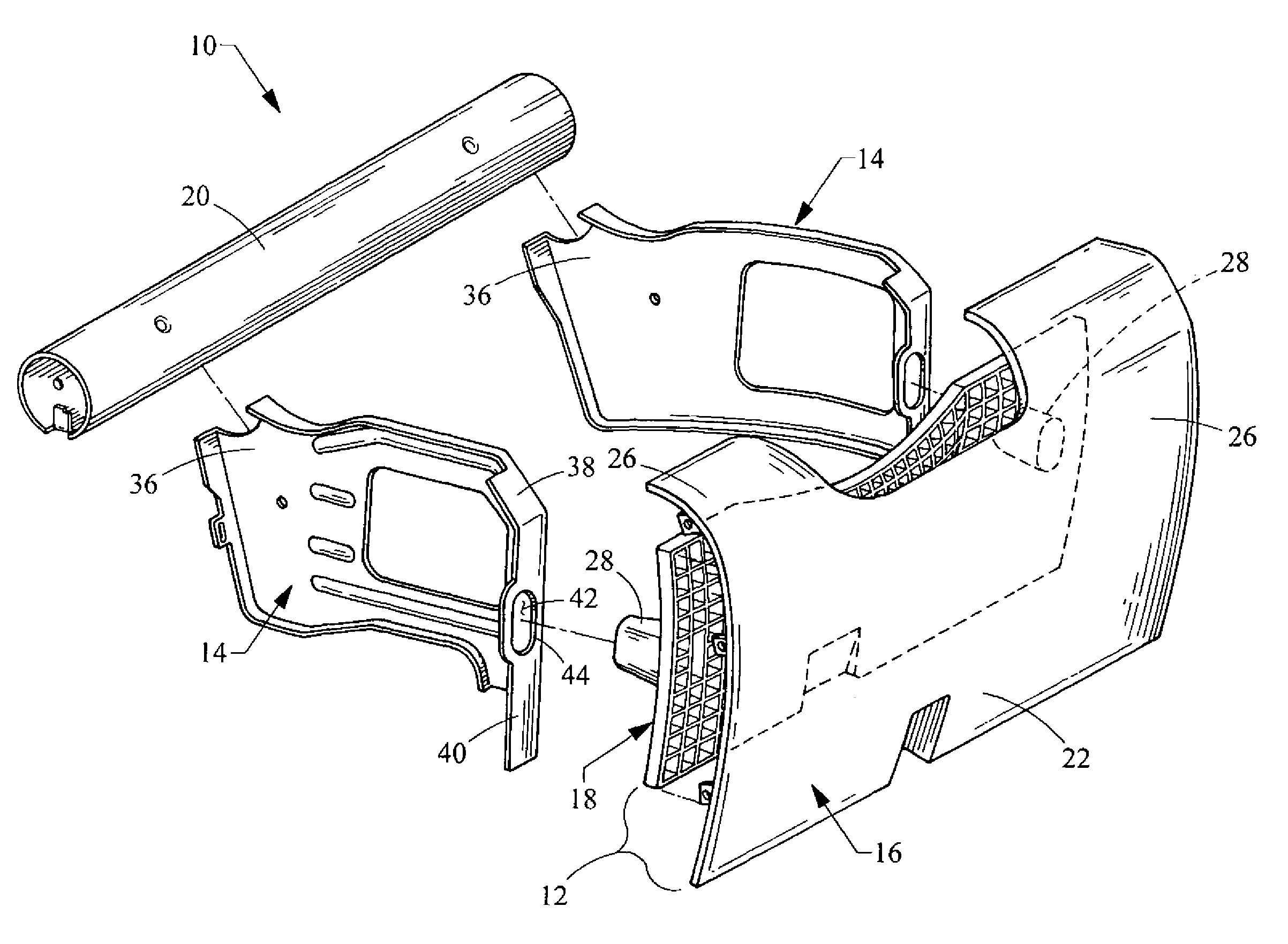
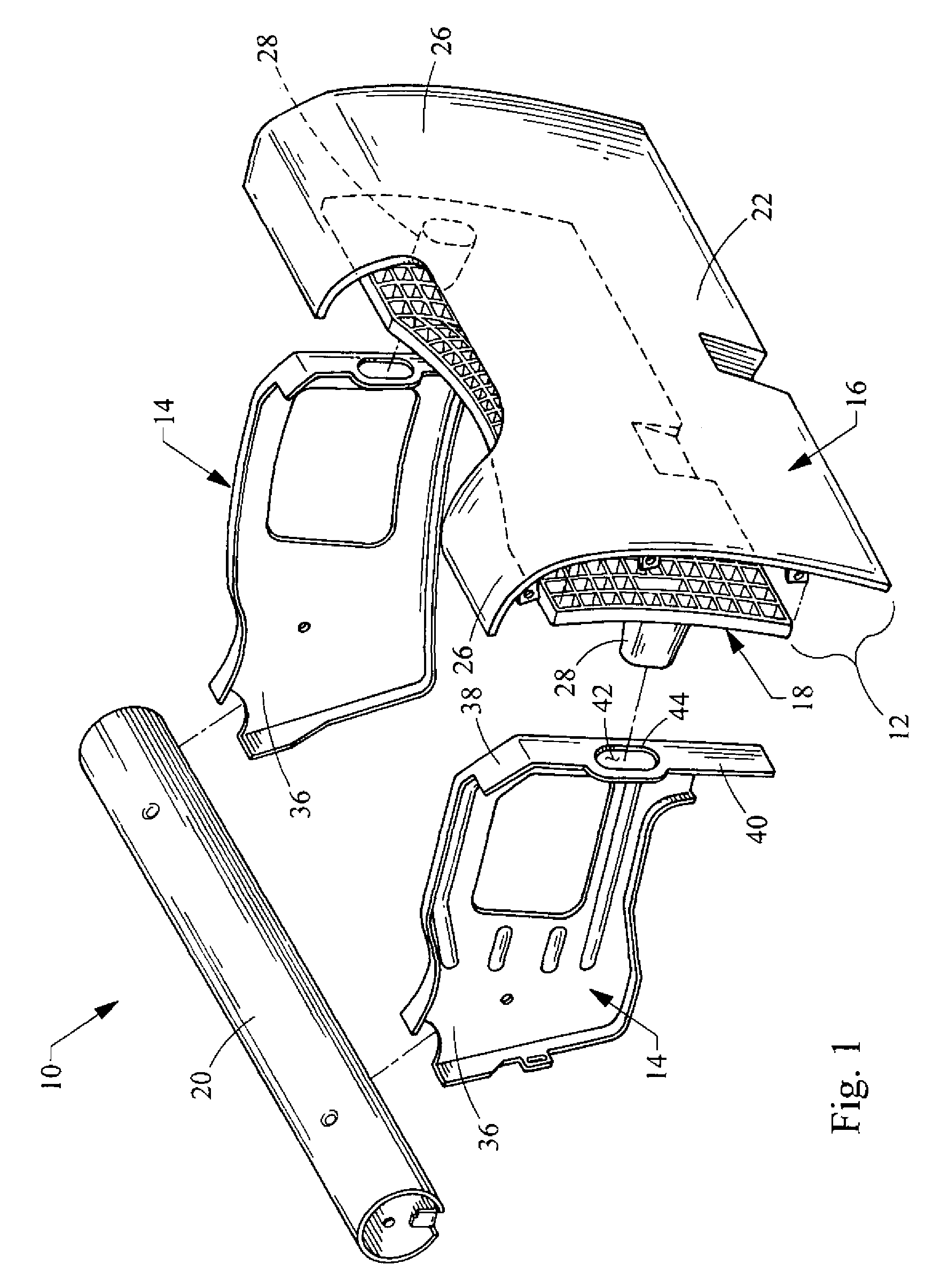
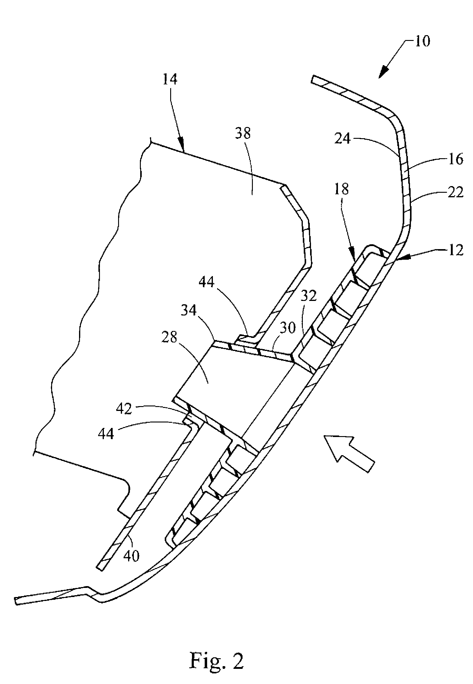
[0015]Referring now the drawings, a knee bolster assembly embodying the principles of the present invention is illustrated therein and generally designated at 10. As its principal components, the knee bolster assembly 10 includes a knee bolster 12 and one or more energy absorbing structures (“EA structure”) 14, two of which are used in the illustrated embodiment. The knee bolster 12 itself may be formed of two components, a skin 16 and an inner panel 18.

[0016]The knee bolster assembly 10 is installed and forms part of an instrument panel of an automotive vehicle. As such, the knee bolster assembly is disposed in the occupant compartment of the vehicle, generally in front of and facing toward the front seats of the vehicle. More specifically, a separate knee bolster assembly is disposed in front of both the front driver seat and front passenger seat. As shown and further described herein, the knee bolster assembly 10 is depicted as one intended to be provided in front of the driver s...


PUM


Abstract

A knee bolster, disposed within the instrument panel of an automotive vehicle, for absorbing energy from impact with the knees of an occupant of the automotive vehicle, the knee bolster assembly comprising a skin defining a show surface of the instrument panel, an inner panel secured to the skin, the inner panel including at least one male portion protruding therefrom in a direction away from the skin, at least one energy absorbing structure extending in a direction away from the inner panel, the energy absorbing structure having portions defining at least one recess therein, the male portions of the inner panel being received within the recess of the energy absorbing structures in a non-contacting alignment.

Description

BACKGROUND OF THE INVENTION[0001]1. Field of the Invention[0002]The present invention relates to a knee bolster, for an automotive vehicle, that absorbs the energy of impact that occurs between the instrument panel of the vehicle and the knees of an occupant during a collision. More specifically, the present invention relates to a knee bolster construction in which relative movement between the knee bolster and its associated energy absorbing structure is substantially eliminated.[0003]2. Description of Related Technology[0004]Knee bolsters are provided in the lower portions of an instrument panel, generally facing the legs of the passengers residing in the front seats of the automotive vehicle. During frontal impacts, one criteria for acceptable knee bolster performance is the effectiveness of the knee bolster in transferring impact loads to an energy absorbing structure located within the instrument panel. To accomplish this objective, the force exerted on the knee bolster, by the...

Claims


Application Information

Patent Timeline
Patent Type & Authority Patents(United States)
IPC IPC(8): B60R21/045
CPCB60R21/045B60R2021/0051
Inventor CAPPABIANCA, DOUGLAS MICHAELCAMILLETTI, III, JOSEPH ANTHONYHUANG, ZHENJIANST. ANGELO, PAUL GREGORY
Owner SMRC AUTOMOTIVE HLDG NETHERLANDS BV
Why Eureka
Try Eureka