Recording apparatus

a recording apparatus and recording technology, applied in the field of recording apparatuses, to achieve the effect of miniaturization

Inactive Publication Date: 2010-06-15
CANON KK
View PDF9 Cites 21 Cited by
  • Summary
  • Abstract
  • Description
  • Claims
  • Application Information

AI Technical Summary

Benefits of technology

[0010]An object of the present invention is to provide a recording apparatus that is advantageous in miniaturization even when a mechanism for adjusting a head gap is included.

Problems solved by technology

There is a case where the construction including such the space is disadvantageous in miniaturization of the recording apparatus, and the conventional recording apparatus has room for improvement in this regard.

Method used


Image

  • Recording apparatus
  • Recording apparatus
  • Recording apparatus

Examples


first embodiment

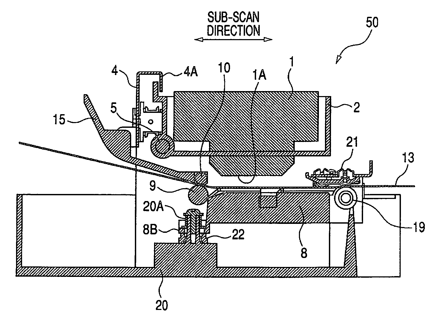
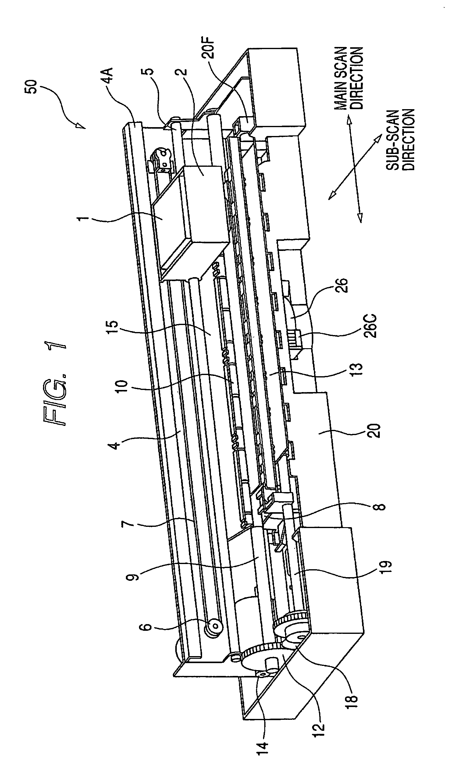
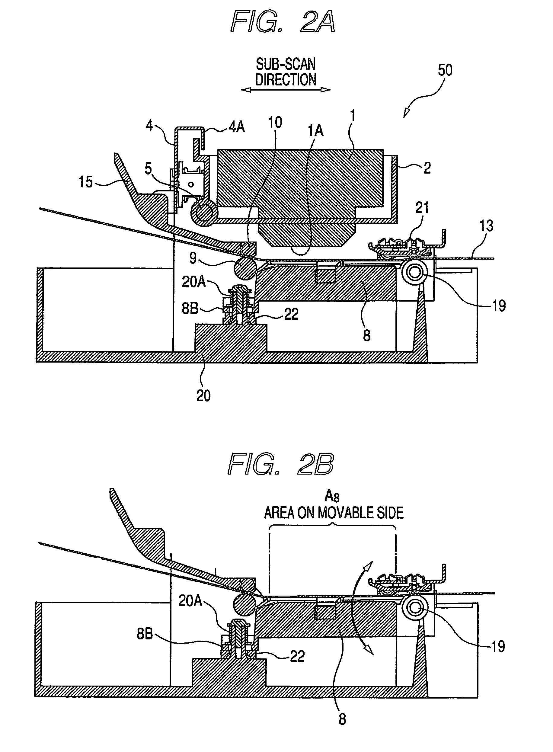
[0026]First, a fundamental construction of a recording apparatus of a first embodiment will be described with reference to FIG. 1 to FIG. 2B. FIG. 1 is a perspective view showing an example of the construction of the recording apparatus to which the present invention is applied. FIGS. 2A and 2B are each a cross-sectional view of the recording apparatus of FIG. 1 in which the recording apparatus is cut in a sub-scan direction, with FIG. 2A showing a state in which a platen is moved upward while FIG. 2B showing a state in which the platen is moved downward.

[0027]As shown in FIG. 1 to FIG. 2B, an ink jet recording apparatus 50 is a recording apparatus of so-called serial scan type that includes a carriage 2 for holding a recording head cartridge 1, multiple rollers 9, 19 and the like for conveying a recording medium 13 in the sub-scan direction, and a platen 8 for supporting a rear surface of the recording medium 13. Note that a main feature of the recording apparatus 50 of this embodi...

second embodiment

[0077]In the first embodiment, the construction in which the platen takes two postures that are the first position and the second position is described as an example, but a construction in which the platen takes three or more postures may be used instead. Also, the postures of the platen are not limited to postures corresponding to a time of recording and may include a posture described below, for instance. The posture will be described below with reference to FIGS. 12 and 13.

[0078]Conventionally, there is a case where in a recording apparatus of this type, under a packed state of the recording apparatus for conveyance to the user, a carriage 2 moves in a main scan direction due to a shock at the time of the conveyance or the like and the recording apparatus gets out of order. In view of this problem, in a recording apparatus shown in FIGS. 12 and 13, a carriage engagement portion 8E is provided for a platen 8 and two engagement portions 2A are provided for the carriage 2. The carri...


PUM


Abstract

A recording apparatus is advantageous in miniaturization even though a mechanism for adjusting a head gap is included. The recording apparatus includes a carriage for detachably holding a cartridge, a platen for supporting one surface of a recording medium, and a conveying roller and an eject roller for conveying the recording medium. The platen is constructed so that it is rockable with an axis of the eject roller as a rotation center and is switchable between at least two positions.

Description

BACKGROUND OF THE INVENTION[0001]1. Field of the Invention[0002]The present invention relates to a recording apparatus adopting, for instance, an ink jet system, and more particularly, to a recording apparatus constructed so that a distance (head gap) between a platen and a recording head can be adjusted.[0003]2. Related Background Art[0004]Conventionally, an ink jet recording apparatus is known which has a construction including a carriage for holding a recording head, a platen for supporting one surface (rear or back surface) of a recording medium in an area opposing a discharge port surface of the recording head, and several rollers for conveying the recording medium.[0005]In the recording apparatus, a predetermined distance (hereinafter referred to as “head gap”) is secured between the recording medium supported on the platen, and the discharge port surface of the recording head and recording is performed by discharging ink from the recording head toward the recording medium in ...

Claims


Application Information

Patent Timeline
Patent Type & Authority Patents(United States)
IPC IPC(8): B41J2/01
CPCB41J11/20
Inventor ASANO, SHINYA
Owner CANON KK
Why Eureka
Try Eureka