Magnetic disk and manufacturing method thereof

a technology of magnetic disks and manufacturing methods, applied in the field of magnetic disks, can solve the problems of adversely affecting the magnetic head, further reducing the magnetic head volume, etc., and achieve the effect of recording/reproduction

Active Publication Date: 2010-06-15
WESTERN DIGITAL TECH INC
View PDF17 Cites 69 Cited by
  • Summary
  • Abstract
  • Description
  • Claims
  • Application Information

AI Technical Summary

Benefits of technology

[0012]In the light of these situations, the present inventor has attempted to develop a magnetic disk which can perform safely recording / reproduction without causing crashing, fly-stiction, and so forth, even when flying flight is performed with a flying amount of 10 nm or less of the magnetic head.
[0013]That is, the present invention has been made to solve such problems, and to provide a magnetic disk which can perform safely recording / reproduction even when flying flight is performed with a flying amount of 10 nm or less of the magnetic head, and the manufacturing method thereof.
[0016]Consequently, when performing studies focusing on the protective layer, the present inventor has found out that with the protective layer formed on the side surface portion of the magnetic disk, particles readily occur as described above, and causal relationship exists between occurrence of the particles and the film thickness of the protective layer of the magnetic disk. In particular, with an environment wherein the above mobile HDD is used, occurrence of particles is readily accelerated, which is inferred.

Problems solved by technology

This is because the flying amount of the magnetic head further decreases as compared with the conventional flying amount, and accordingly, protruding portions which have not been seen as problematic conventionally since no trouble was caused thereby, adversely affect the magnetic head.

Method used


Image

  • Magnetic disk and manufacturing method thereof
  • Magnetic disk and manufacturing method thereof
  • Magnetic disk and manufacturing method thereof

Examples


example 1

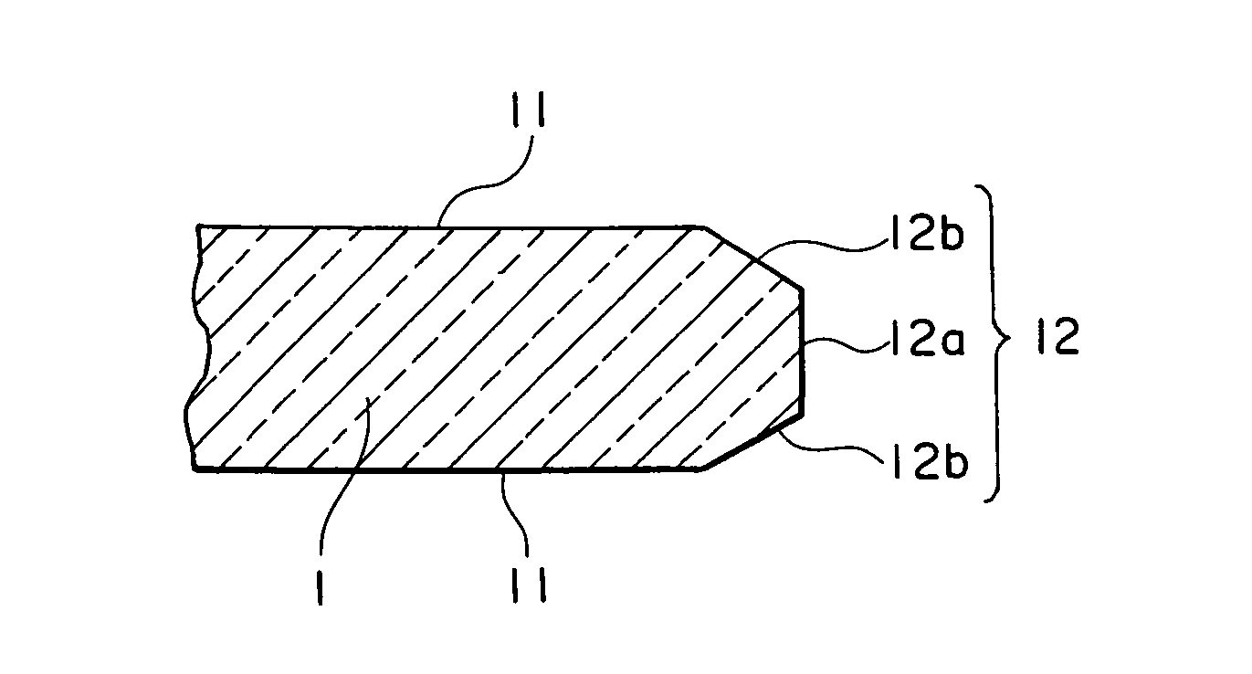
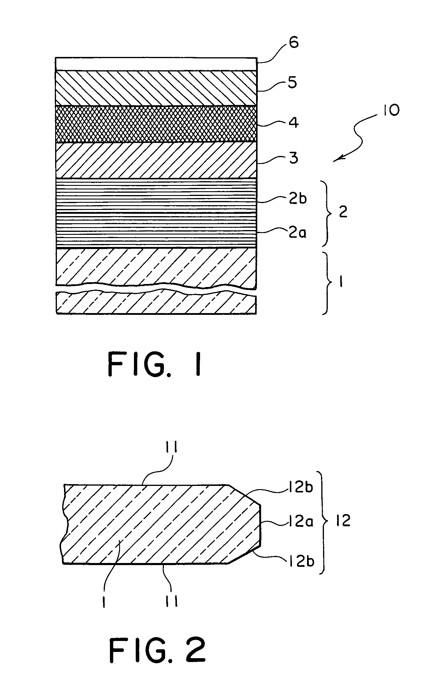
[0065]As shown in FIG. 1, the magnetic disk 10 according to the present example is configured by layering a seed layer 2, a base layer 3, a magnetic layer 4, a protective layer 5, and a lubricant layer 6 in order on a glass substrate 1.

[0066]In the present example 1, first, a glass substrate made up of plate-shaped aluminosilicate glass with 66 mm diameter and 1.5 mm thickness was obtained from dissolved glass by direct press using an upper mold, lower mold, and chest mold, and the obtained glass was subjected to a rough lapping process (rough grinding process), shape forming process, precise lapping process (precise grinding process), end surface mirror surface forming process, and principal surface mirror surface polishing process in order, and subsequently subjected to chemical strengthening, thereby manufacturing the glass substrate 1 for a magnetic disk. With this glass substrate 1, the principal surface and the end surface were both subjected to mirror surface polishing.

[0067]...

examples 2 through 4

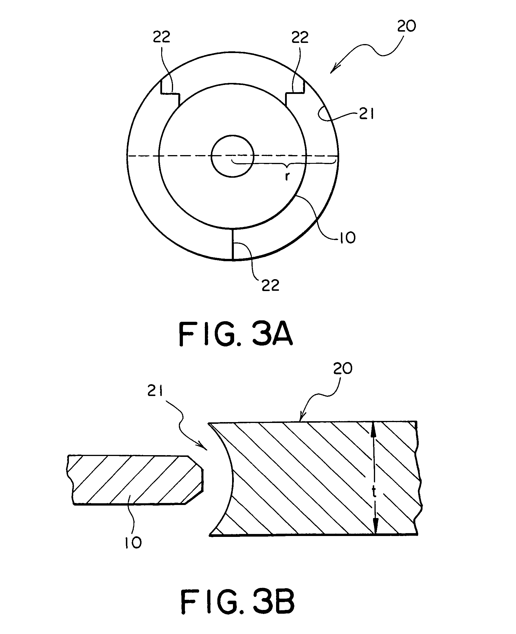
[0079]Magnetic disks according to the present examples 2 through 4 were manufactured using glass substrates with outer diameters of 48.0 mm, 27.4 mm, and 21.6 mm respectively in the same way as with the example 1 except that the holders having shapes shown in Table 1 were employed at the time of forming the protective layers. Note that the film thicknesses of the protective layers are shown in the above Table 2.


PUM

PropertyMeasurementUnit
thicknessaaaaaaaaaa
thicknessaaaaaaaaaa
thicknessaaaaaaaaaa

Abstract

A magnetic disk comprises a magnetic layer and a protective layer sequentially formed on a disk-shaped substrate and has a principal surface to which data is recorded, and a side surface portion both of which are coated with the protective layer. The protective layer on the side surface portion is thinner than the protective layer on the principal surface. Preferably, the side surface portion includes a side wall surface, and a chamfered surface lying between the side wall surface and the principal surface, and at least the protective layer on the chamfered surface is thinner than the protective layer on the principal surface.

Description

[0001]This application claims priority to prior Japanese patent application JP 2004-283137, the disclosure of which is incorporated herein by reference.BACKGROUND OF THE INVENTION[0002]The present invention relates to a magnetic disk to be mounted on a magnetic disk device, such as a hard disk drive (HDD) and the like, for recording information, and the manufacturing method thereof.[0003]Conventionally, with a magnetic disk device, at a halt stage, a CSS (Contact Start and Stop) method has been employed wherein a magnetic head is kept in contact with an inner circumferential region surface for contact sliding on the magnetic disk. At a start-up stage, the magnetic head is slightly raised while sliding in contact with this inner circumferential region surface to start recording / reproduction at a region for recording / reproduction outside of the inner circumferential region surface for contact sliding. With this CSS method, the region for contact sliding needs to be secured on the magn...

Claims


Application Information

Patent Timeline
Patent Type & Authority Patents(United States)
IPC IPC(8): G11B5/72G11B5/82G11B5/84
CPCG11B5/72G11B5/8408G11B5/82G11B5/727
Inventor ISHIYAMA, MASAFUMI
Owner WESTERN DIGITAL TECH INC
Why Eureka
Try Eureka